TM 9--2815--247--34
0085 00--21
ACCESSORY DRIVE HOUSING ASSEMBLY AND ASSOCIATED PARTS
REPAIR -- CONTINUED
0085 00
Adjustment -- Continued
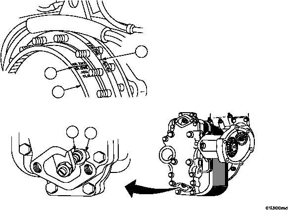
12. Check valve timing by rotating flywheel (66) clockwise, as viewed from the flywheel end, approximately 1/8 turn to
remove gear backlash, then turn counterclockwise until the intake valve (72) is just closed. Stop rotating the fly-
wheel (66) the instant the valve adjusting screw swivel pad (73) becomes free.
13. Observe position of flywheel timing mark “6R INT. CLOSE .100 CLR” (68). When timing mark (68) is aligned with-
in 1/8 inch (3.1750 mm) of engine timing mark (67), the valve timing is correct. If timing mark is not aligned within
1/8 inch (3.1750 mm), withdraw shouldered shaft and repeat steps 9 through 13.
NOTE
When correct timing cannot be obtained as described
above, it may be necessary to set timing mark (68), 1/8 to
1/4 inch (3.1750 -- 6.3500 mm) out of alignment with en-
gine timing mark (67), before installing shouldered shaft.
Figure 9
68
66
67
73
72 (HIDDEN)
|
|