|
|
|
|

|
TM 9--2815--247--34
0085 00--24
ACCESSORY DRIVE HOUSING ASSEMBLY AND ASSOCIATED PARTS
REPAIR -- CONTINUED
0085 00
Adjustment -- Continued
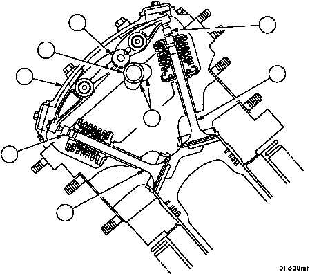
18. Apply lubricant to camshaft bearings and install left bank camshaft (83) so that cylinder No. 6L cam lobes (70) are
pointing downward toward the crankshaft centerline. Refer to WP 0076 00.
19. Install cylinder No. 6L rocker arm cover (71). Refer to WP 0026 00.
20. Adjust clearance between intake valve (72) and valve adjusting screw swivel pad (73) to 0.100 inches (2.54 mm).
Adjust clearance between exhaust valve (74) and valve adjusting screw swivel pad (75) to 0.025 inches (0.635
mm). Refer to WP 0014 00.
21. Position the camshaft (83) so cylinder No. 2L cam lobes (70) are pointing downward toward the crankshaft center-
line.
22. Install cylinder No. 2L rocker arm cover (71). Refer to WP 0026 00.
23. Adjust the clearance between intake valve (72) and valve adjusting screw swivel pad (73) to 0.100 inches (2.54
mm). Adjust the clearance between exhaust valve (74) and valve adjusting screw swivel pad (75) to 0.025 inches
(0.625 mm). Refer to WP 0014 00.
24. Rotate left camshaft (83) clockwise (as viewed from flywheel end) until cam follower (76) has opened and closed
intake and exhaust valves (72 and 74) of cylinder 6L.
Figure 10
74
75
76
83
71
73
72
70
|
|
|
|
|
Privacy Statement -
Copyright Information. -
Contact Us