|
|
|
|

|
TM 9--2815--247--34
0088 00--9
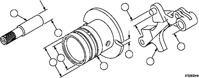
AUTOMATIC FUEL INJECTION ADVANCE CONTROL ASSEMBLY AND
ASSOCIATED PARTS REPAIR -- CONTINUED
0088 00
Inspection -- Continued
3. Measure outside diameter (44) of two threaded pins (24). Replace threaded pins if not within the following limits.
4. Measure inside diameter (45) of hole in two flyweight assemblies (17). Replace flyweight assemblies if not within
the following limits.
5. Measure outside diameter (46) of pin on two flyweight assemblies (17). Replace flyweight assemblies if not within
the following limits.
6. Measure outside diameter (47) of fluid regulating valve (26). Replace fluid regulating valve if not within the follow-
ing limits.
7. Measure inside diameter (48) of fluid regulating valve (26). Replace fluid regulating valve if not within the follow-
ing limits.
8. Measure width of slots (49) in fluid regulating valve (26). Replace fluid regulating valve if not within the following
limits.
REF
NO.
POINT OF MEASUREMENT
SIZES AND FITS OF NEW PART
inches (mm)
WEAR LIMITS
44
Outside diameter of threaded
pins
0.3110 (7.8994)
0.3115 (7.9121)
0.3105 (7.8867)
45
Inside diameters of holes in fly-
weight assemblies
0.3120 (7.9248)
0.3130 (7.9502)
0.3140 (7.9756)
46
Outside diameter of pins on fly-
weight assemblies
0.2500 (6.3500)
0.2510 (6.3754)
0.2490 (6.3246)
47
Outside diameter of fluid regulat-
ing valve
1.8710 (47.5234)
1.8715 (47.5361)
1.8708 (47.5183)
48
Inside diameter of fluid regulating
valve
1.5015 (38.1381)
1.5020 (38.1508)
1.5030 (38.1762)
49
Width of slots in fluid regulating
valve
0.2510 (6.3754)
0.2550 (6.4770)
0.2560 (6.5024)
24
17
26
44
47
48
49
46
45
Figure 33
|
|
|
|
|
Privacy Statement -
Copyright Information. -
Contact Us