TM 9-2815-250-24&P
3-19. FLOW CONTROL VALVE ADJUSTMENT.
This Task Covers:
Adjustment
Initial Setup:
Tools/Test Equipment:
Gasket (2) (Item 16, Appendix F)
Fuel-test set (Item 12, Appendix G)
O-ring (2) (Item 17, Appendix F)
Fuel-testing device (Item 13, Appendix G)
General mechanic's tool kit
Equipment Conditions:
(Item 14, Appendix G)
Airflow deflectors removed as needed (para 2-24).
Indicator dial (Item 16, Appendix G)
Fuel pressure pipes removed (para 2-23).
Wrench (Item 36, Appendix G)
Vehicle fuel supply connected to injection
pump (refer to TM 9-2350-293-20).
Materials/Parts:
Rubber band (Item 8, Appendix D)
Crankcase gasket set (Item 1, Appendix F)
ADJUSTMENT
NOTE
· The flow control valve should be adjusted only if any of the following conditions
exist: The flow control valve has been replaced; the engine lacks power; or the
engine emits smoke after start-up, during operation.
· The fuel quantity injected is determined by the travel of the pump plunger
between start and end of delivery. This dimension is specified in millimeters on
the engine data plate located on the flywheel air duct.
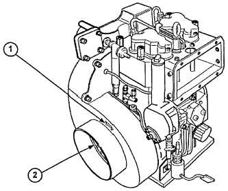
a.
Turn flywheel (2) clockwise until 26-degree mark on flywheel (2) is aligned with "PM" mark on flywheel airflow
deflector (1).
3-60
|
|