|
|
|
|

|
TM 9-2815-250-24&P
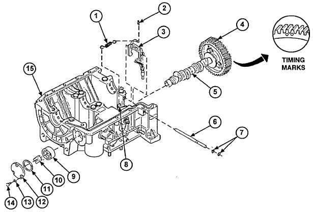
3-11. CAMSHAFT REPAIR (continued).
13.
Install pin (6) on governor control lever assembly (3) and upper crankcase (15).
14.
Install governor spring (1) on governor control lever assembly (3) and accelerator lever (8). Secure governor spring
(1) with new clip (2).
15.
Place oil pump gear (10) and rotor (9) in upper crankcase (15). Make sure beveled edge of rotor (9) is facing
toward inside of upper crankcase (15).
16.
Install new O-ring (11) in oil pump cover (12).
17.
Install oil pump cover(1 2) on upper crankcase (15) and secure with three screws (14) and washers (13). Turn
camshaft gear (4) to be sure camshaft assembly (5) turns freely.
FOLLOW-ON TASKS:
Assemble crankcase (para 3-6).
3-45
|
|
|
|
|
Privacy Statement -
Copyright Information. -
Contact Us