ARMY TM 92815-252-24
AIR FORCE TO 38G1-92-2
g.
Turn engine over manually to establish TDC between compression and power strokes for cylinder being timed.
Normal engine direction of rotation is clockwise as viewed from the fan end. Correct top center occurs approximately
140 degrees of crankshaft rotation after intake valve closes.
h.
Remove intake valve rocker lever nut and rocker lever, refer to paragraph 3-26.1.
Warning
Do not stand over valve springs when depressing valves. Failure to observe this warning could
result In personal injury.
i.
Using valve spring tool, depress intake valve until it contacts the piston crown (approximately 0.051 to 0.059
inches [1.3 to 1.5 mm]). Then remove collets, carrier, and spring from intake valve.
NOTE
If valve can be depressed more than approximately 0.25 in. (6.35 mm), piston is not in correct
position. Engine should be rotated to correct position to avoid possibility of dropping valve into
cylinder once carrier and spring are removed
j.
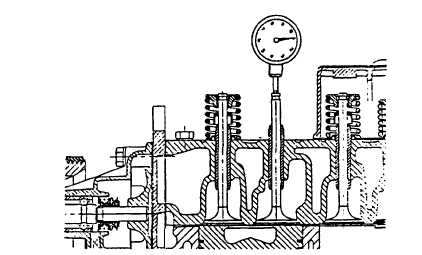
Valve can now be depressed until head of valve rests on top of piston, refer to FIGURE 3-10.
k.
Mount a dial indicator, refer to FIGURE 3-10, to cylinder head to check intake valve drop. Carefully turn engine
a small amount either side of TDC and dial indicator can be zeroed at TDC.
FIGURE 3-10. Checking Piston Drop
I.
Measure piston drop. Engine should then be rotated opposite normal crankshaft rotation (counterclockwise as
viewed from fan end) to approximately 0.01 in. (0.2544 mm) drop beyond specified piston drop of 0.99 in.
(2.519 mm). Then rotate in direction of normal crankshaft rotation until specified piston drop is reached. It is
important that specified piston drop be approached in direction of normal crankshaft rotation.
NOTE
It may be necessary to push down on valve stem to overcome friction of stem seal and maintain
contact of valve head to piston crown.
3-27
|
|


