ARMY TM 92815-252-24
AIR FORCE TO 38G1-92-2
NOTE
Ensure top face of crankcase is clean.
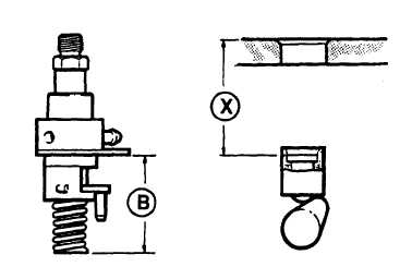
m. Using a depth gage, measure distance (X) from top face of crankcase to top of fuel pump tappet cap, refer to
FIGURE 3-11. Subtract dimension (X) from dimension (B) 2.02 in. (51.196 mm) to obtain required thickness of
shim pack to be installed between fuel injection pump plate and crankcase.
n.
Install intake valve spring, carrier, and collets, refer to paragraph 3-27.5.
o.
Install rocker lever and rocker lever nut, refer to paragraph 3-26.3.
FIGURE 3-11. FUEL INJECTOR Pump Dimensions
NOTE
Hydraulic tappet bleed down must be verified before proceeding, refer to paragraph
p.
Install fuel injection pump, refer to paragraph 3-13.4..
q.
Install fuel injector and fuel injector pipe, refer to paragraphs 3-17.4. and 3-18.3.
r.
Install cylinder head cover, refer to paragraph 3-25.3.
3-15.
FUEL SUPPLY LINES.
3-15.1. Removal.
a.
Loosen clamps (4, FIGURE 3-7) and disconnect supply hoses of fuel line (11) from fuel injection pumps (5).
b.
Disconnect fuel return hose from fuel supply line (11).
c.
Remove swivel union plug (9) securing fuel line (11) to fuel filter (15); remove fuel line (11) and two seals (10).
Discard seals (10)
d.
Cap all openings.
3-15.2
Inspection.
a.
Inspect metal portions of fuel line for dents or deformations.
b.
Inspect hoses of fuel line for cracks, deterioration, or any other damage.
3-28
|
|