ARMY TM 9-2815-253-24
AIR FORCE TO 38G1-93-2
MARINE CORPS TM 2815-24/3
d.
Press down on top of thrust cup (8) and fuel pump tappet (7) and slowly turn crankshaft until fuel pump tappets
felt to be at its lowest position.
e.
Remove gear end cover. Refer to paragraph 3-28.1 and remove rack spring (15, FIGURE 3-19) from governor
lever.
f.
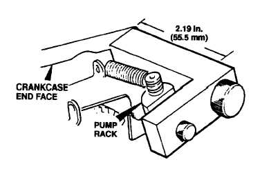
Using fuel pump rack setting gage (317-50114), damp pump rack in shutdown position. Screw on gage threads
into end cover tapped hole. Refer to FIGURE 3-9.
FIGURE 3-9. Setting Pump Rack
g.
If removed, install stud (3, FIGURE 3-7).
h.
Install correct original shim pack (6) on fuel pump (5).
(1)
Do not remove or add to original shims installed between pump flange and steel plate.
(2)
Use extreme care to ensure that individual shim packs are installed between each fuel pump plate and
crankcase and that they are retained with their original respective cylinder.
(3)
Shims are available in three sizes and are color coded. Refer to TABLE 3-3.
TABLE 3-3. Color Coded Shim Packs for Fuel Pump
Color
Size
Green
0.003 in. (0.075 mm)
Slate Blue
0.005 in. (0.125 mm)
Black
0.010 in. (0.250 mm)
3-22
|
|