ARMY TM 9-2815-253-24
AIR FORCE TO 38G1-93-2
MARINE CORPS TM 2815-24/3
3-20.2.3 Inspection.
a.
Inspect dipstick (12, FIGURE 3-15) for legibility. Replace if damaged.
b.
Inspect performed packings (13 and 11) for deterioration and replace as necessary.
c.
Inspect crankcase door (7) for cracks, dents, or other damage. Replace if damaged.
d.
Inspect adapter (2) for thread damage and replace as necessary.
3-20.2.4 Installation.
a.
Ensure crankcase door and crankcase mating surfaces are dean and dry.
b.
If removed, install tappet studs (9, FIGURE 3-15) in engine block Refer to FIGURE 3-8 for proper alignment with
tappet slot and tappet movement.
c.
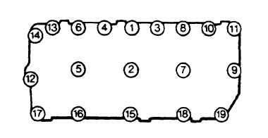
Position new gasket (8) and crankcase door (7) on crankcase and secure with eleven bolts (3), four nuts (5) and
two standoff studs (6) with nineteen washers (4). Tighten bolts (3) to 78 in-lbs (8.8 Nm) in sequence shown in
FIGURE 3-16.
d.
Install fuel solenoid and bracket. Refer to paragraph 3-19.4.
e.
Install oil filter cartridge. Refer to paragraph 3-20.1.
f.
Service lubrication system. Refer to end item lubrication order.
g.
Operate engine and check for leakage.
FIGURE 3-16. Crankcase Door Fastener Tightening Sequence
3-21. OIL PUMP AND STRAINER.
3-21.1. Removal.
a.
Drain lubrication system. Refer to end item maintenance manual.
b.
Remove camshaft. Refer to paragraph 3-29.1.
c.
Remove crankcase door. Refer to paragraph 3-20.2.1.
d.
From inside crankcase, unscrew oil pressure relief valve (1, FIGURE 3-17) from oil pump (5).
e.
Unscrew strainer (2) coupling nut from oil pump (5).
f.
Remove two capscrews (3) and washers (4) securing oil pump (5); remove oil pump.
3-34
|
|