|
|
|
|

|
ARMY TM 9-2815-253-24
AIR FORCE TO 38G1-93-2
MARINE CORPS TM 2815-24/3
3-21.2. Inspect and Test.
a.
Inspect pump for freedom of movement by turning gear.
b.
Check oil pressure relief valve setting using hydraulic test stand. Valve should relieve at 47 to 59 psi (324 to 407
kPa).
c.
Inspect strainer for blockage and clean as necessary.
d.
Inspect all parts for wear or damage and replace defective components.
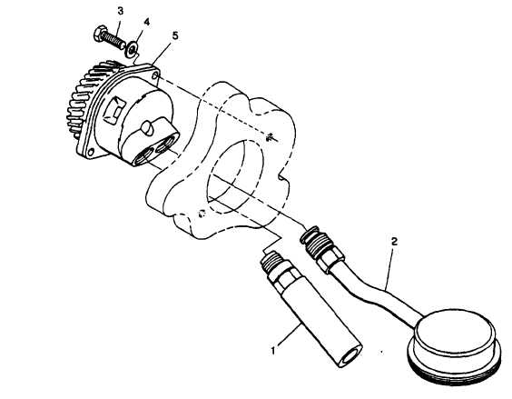
3-21.3. Installation.
a.
Position oil pump (5, FIGURE 3-17) in crankcase with cutout section of pump behind gear facing top of
crankcase.
b.
Secure oil pump (5) with two capscrews (3) and washers (4). Tighten capscrews to 78 in-lbs (8.8 Nm).
c.
Install oil strainer (2) in right pump port with strainer gauze parallel with sump base. Tighten retaining nut.
d.
Install relief valve (1) in left pump port and tighten retaining nut.
e.
Install crankcase door. Refer to paragraph 3-20.2.4.
f.
Install camshaft. Refer to paragraph 3-29.3.
g.
Service lubrication system. Refer to end item lubrication order.
h.
Operate engine and check for proper operation and for leakage.
FIGURE 3-17. Strainer and Oil Pump
3-35
|
|
|
|
|
Privacy Statement -
Copyright Information. -
Contact Us