ARMY TM 9-2815-253-24
AIR FORCE TO 38G1-93-2
MARINE CORPS TM 2815-24/3
g.
Install cover (10) and secure with two screws (9).
h.
Install armature (8) in center bracket (15).
i.
Install brushes in brush holder assembly (5).
j.
Position frame assembly (7) on center bracket (15). Tab on frame assembly (7) must fit in notch in center
bracket.
k.
Pull brushes upward and install brush holder assembly (15) on frame assembly (7). Ensure brushes in brush
holders seat against commutator bars.
l.
Position rear bracket (6) and secure brush holder assembly (5) to rear bracket (6) with two screws (4).
m.
Install two through bolts (3).
NOTE
Be sure that rectangular hole in solenoid (1) plunger shaft engages lever (21) in housing.
NOTE
Apply sealing compound (MIL-R-46082) to screws (2) before assembly.
n.
Install solenoid (1) and secure with screws (2).
o.
Reconnect wire to solenoid. Remove tag.
p.
Check pinion gap as follows:
(1)
Connect a 24 VDC power source positive lead to terminal 'S' on solenoid and negative lead to starter
frame.
(2)
Apply power to solenoid and pinion gear will shift.
(3)
Disconnect terminal 'M' wire to stop pinion from rotating.
(4)
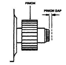
Gently push pinion shaft towards solenoid and measure amount of travel. Refer to FIGURE 3-26. Pinion
gap should be 0.0118 to 0.787 in. (0.3 to 2.0 mm).
(5)
Adjust gap by increasing or decreasing number of fiber washers between solenoid and front bracket.
Increasing number of washers decreases gap and decreasing number of washers increase gap.
3-24.6. Installation.
a.
Remove cover in flywheel housing.
b.
Position starter in flywheel housing and secure with two capscrews (5, FIGURE 3-21) and washers (6). Tighten
capscrews to 30 ft-lbs (40.7 Nm).
c.
Connect wires to starter as tagged during removal using capscrew (3), new lockwasher (4), nuts (1), and new
lockwashers (2). Remove tags.
FIGURE 3-26. Checking Pinion Gap
3-46
|
|


