ARMY TM 9-2815-253-24
AIR FORCE TO 38G1-93-2
MARINE CORPS TM 2815-24/3
NOTE
If pinion gear is worn or damaged, inspect flywheel ring gear also.
f.
Inspect armature shaft gear, bearings, reduction gear, and pinion gear for wear or damage. Replace any part
that is damaged.
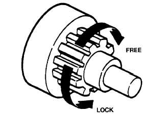
g.
When pinion gear is placed upon overrunning clutch, pinion gear should turn freely in one direction and lock
when turned in opposite direction. Refer to FIGURE 3-25.
FIGURE 3-25. Overrunning Clutch
3-24.5. Assembly.
a.
Apply a light coating of general purpose grease (630AA) to following starter components before assembling.
(1)
Armature (8, FIGURE 3-22) shaft gear.
(2)
Gear (18).
(3)
Armature shaft bearings.
(4)
Stopper (24).
(5)
Sleeve bearing in front bracket (16).
(6)
Pinion gear (25).
(7)
Lever (21) sliding portion.
(8)
Solenoid (1) plunger.
b.
Position overrunning clutch (22) into front bracket (16).
c.
Install spring (26) and pinion gear (25) on overrunning clutch shaft.
d.
Slide stopper (24) onto shaft and install new retaining ring (23) in groove. Stopper (24) must fully engage
retaining ring when installed.
e.
Install lever (21) (as noted during removal), spring set (19), and packing (20).
f.
Adjust pinion shaft end play as follows:
(1)
Place gear (18) on pinion shaft.
(2)
Install center bracket (15) and secure with screw (14).
(3)
Install new gasket (13), washer (12), and new retaining ring (11).
(4)
Measure pinion shaft end play with a feeler gage between center bracket (15) and washer (12).
(5)
Adjust end play to between 0.0039 to 0.020 in. (0.1 to 0.5 mm) with adjustment washers (17).
3-45
|
|