ARMY TM 9-2815-253-24
AIR FORCE TO 38G1-93-2
MARINE CORPS TM 2815-24/3
CAUTION
Ensure that no piston is at TDC when replacing head. Failure to follow this procedure could cause
misalignment of the head.
h.
Install a new gasket (7) and cylinder head (6) over guide studs. Ensure that pushrod tubes (8) are properly
aligned with head.
i.
Remove cylinder head guide studs.
NOTE
There are three types of cylinder head bolts used. Install them in their proper locations as noted
during removal.
j.
Install four bolts (3), four bolts (4), and eight washers (5). Refer to FIGURE 3-278 and install eight bolts (7) and
spacers (8). Tighten all bolts finger tight.
k.
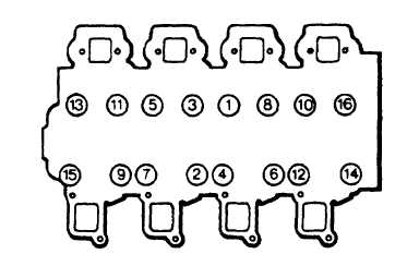
Tighten all sixteen bolts in three stages and in sequence shown in FIGURE 3-31.
(1)
First tighten to 6.2 ft-lbs (8.4 Nm).
(2)
Second tighten to 38.5 ft-lbs (52.2 Nm).
(3)
Final tighten to 66.6 ft-lbs (90.3 Nm).
l.
Install rocker levers and pushrods. Refer to paragraph 3-26.3.
m.
Install cylinder covers. Refer to paragraph 3-25.3.
n.
Position lifting eyes (2, FIGURE 3-28) on bolts (4) and secure with nuts (1).
o.
Install fuel injectors. Refer to paragraph 3-17.4.
p.
Install fuel injector pipes. Refer to paragraph 3-18.3.
q.
Install exhaust manifold. Refer to paragraph 3-7.3.
r.
Install intake manifold. Refer to paragraph 3-6.3.
FIGURE 3-31. Cylinder Head Bolt Tightening Sequence
3-55
|
|