ARMY TM 9-2815-254-24
AIR FORCE TO 38G1-94-2
e.
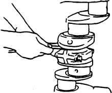
Check connecting rod side face clearance as follows:
(1) Install connecting rod on crankpin.
(2) Using a feeler gage, measure clearance between connecting rod side face and crankpin web face, refer
to FIGURE 3-83.
(3) Standard clearance is 0.009 in. (0.23 mm), with a limit of 0.014 in. (0.35 mm).
FIGURE 3-83. Connecting Rod Side Face Clearance
(4) If measured clearance exceeds limit, replace connecting rod.
3-28.3.2
Crankshaft and Bearings.
a.
The following is a summation of basic dimension measurements, refer to FIGURE 3-84.
(1) Measure A and B dimensions, and subtract B from A to obtain dimension C.
(2) Measure crankpin to connecting rod bearing clearance D in same manner.
(3) Clearances C or D are basis for determining crankshaft repairs.
(4) Replace bearings with standard size ones when crankshaft journal wear and/or crankpin wear is within
limits but bearing wear is close to wear limits.
(5) Replace bearings with undersized ones when crankshaft journal wear and crankpin wear exceeds limits.
3-134
|
|


