ARMY TM 9-2815-255-24
AIR FORCE TO 38G1-95-2
MARINE CORPS TM 2815-24/4
CAUTION
Do not handle precision machined rotor surfaces. Damage due to corrosion could occur.
NOTE
In addition to the parts supplied with the repair kits, cam (17, FIGURE 3-45), delivery valve stop
(35, FIGURE 3-52), and connector assembly (1, FIGURE 3-45) must be replaced during assembly.
NOTE
Parts which must be replaced and are not included in the repair kits are lockwashers, delivery
valve stop (35, FIGURE 3-52), insulator washers (15, FIGURE 3-45), and pilot tube (1, FIGURE 3-
52).
a.
Rinse rotor thoroughly in clean diesel fuel or calibrating oil.
b.
Place rotor on weight retainer (31, FIGURE 3-52) and secure in a vise.
NOTE
Do not mistake slight interference of retractor collet in bore for delivery valve sticking. If valve is
not secured straight and tight in retractor collect, collet diameter can drag in rotor bore.
c.
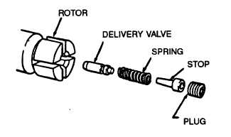
Using extractor (13383), install delivery valve (35) into bore of rotor. Ensure it slides freely in its bore, refer to
FIGURE 3-72.
FIGURE 3-72. Delivery Valve Replacement
CAUTION
Always use a new delivery valve stop (33, FIGURE 3-52). Installation of a used stop can result In
leakage and low output at cranking speed.
3-101
|
|