ARMY TM 9-2815-255-24
AIR FORCE TO 38G1-95-2
MARINE CORPS TM 2815-24/4
j.
Install fixture (19969) in vise (clamping on flat area) so that air inlet hole is not covered by vise. Install a 1/4 18
NPT fitting in air inlet of fixture. Connect fitting to a supply of clean filtered, compressed air, regulated to a
pressure of 40 to 100 psi (275 to 689 kPa).
NOTE
To set roller-to-roller dimension to specification, turn leaf spring screw (25) inward (clockwise) to
increase, and outward (counterclockwise) to reduce roller-to-roller dimension.
k.
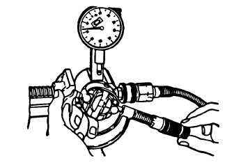
Using a micrometer, measure roller-to-roller dimension (distance between outer surfaces of opposed cam
rollers). Dimension should be 1.9845 to 1.9875 inches (50.032 to 50.118 mm), refer to FIGURE 3-74.
FIGURE 3-74. Measuring Roller-To-Roller Dimension
NOTE
The roller-to-roller setting provides a completely accurate maximum fuel adjustment and it
should not differ from value of 95.5 to 96.5 cu mm/stroke (1564.9 to 1581.3 cm3).
I.
Perform a centrality check as follows. Maximum allowable tolerance is 0.004 inch (0.102 mm).
(1)
After setting roller-to-roller dimension, rotate rotor until one roller is aligned with dial indicator plunger.
Slide indicator inward until plunger depresses it at least 0.010 inch (0.25 mm). Lock indicator retaining
screw zero dial indicator on high point of roller by rotating knurled dial.
(2)
Rotate rotor (either direction) until other roller depresses dial indicator plunger.
(3)
If roller centrality is beyond specified tolerance, roller and/or shoes can be interchanged. Recheck
centrality after each change and recheck roller-to-roller dimension.
m.
Rinse hydraulic head assembly in clean calibrating oil.
n.
Remove rotor assembly from fixture, ensuring shoes and rollers remain in their respective slots. Rinse assembly
in clean calibrating oil.
o.
Insert rotor assembly into hydraulic head.
NOTE
If cam ring (24, FIGURE 3-52) is installed incorrectly, pump will not be in time with engine.
p.
Place cam ring (24) onto rotor assembly with directional arrow indicating direction of pump rotation. (Pump
rotation is as viewed from drive end.)
3-103
|
|