ARMY TM 9-2815-255-24
AIR FORCE TO 38G1-95-2
MARINE CORPS TM 2815-24/4
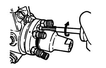
FIGURE 3-88. Installing Retaining Plate (Typical)
cn.
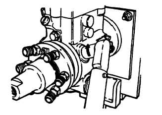
Tighten both head locking bolts (51, FIGURE 3-45) 15 to 18 ft-lbs (20 to 25 Nm), refer to FIGURE 3-89.
FIGURE 3-89. Installing Locking Head Bolts (Typical)
co.
Remove pump from holding fixture.
cp.
Install pilot tube seal (1, FIGURE 3-52) in mounting flange end of pump, refer to FIGURE 3-90.
3-114
|
|