ARMY TM 9-2815-255-24
AIR FORCE TO 38G1-95-2
MARINE CORPS TM 2815-24/4
(2)
Raise pressure to 1500 psi (10,300 kPa) on test gage.
(3)
Look for leakage from return end of nozzle.
(4)
After one drop, leakage should be 3 to 10 drops in 30 seconds. Rate based on use of No. 2 diesel fuel or
an equivalent viscosity of test oil at 65 to 75°F (18 to 24°C) ambient temperature.
(5)
If nozzle leakage is not within specified range, nozzle must be replaced.
3-29.4. Installation.
3-29.4.1 Install Seals On Nozzle.
CAUTION
Each time an injection nozzle is removed from cylinder head, replace carbon stop seal (6,
FIGURE 3-92) with a new one.
a.
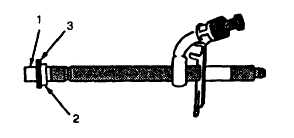
Position protector cap (1, FIGURE 3-93) over nozzle tip. A nozzle protector cap can be found on every new or
replacement nozzle.
b.
Position a new carbon stop seal (2) on protector cap. Use a new seal washer (3) to help slide the carbon seal (2)
into place until it seats in its groove on nozzle body.
c.
Continue to slide seal washer (3) onto nozzle body until it seats against inlet fitting.
FIGURE 3-93. Fuel Injection Nozzle Seals
NOTE
If nozzle is not going to be installed at this time, install a nozzle protector cap over nozzle tip.
Plug all other openings in nozzle to prevent contamination.
3-29.4.2 Install Injection Nozzle.
Warning
Compressed air used for cleaning can create airborne particles that may enter the eyes. Pressure
will not exceed 30 psig (207 kPa). Eye protection required.
CAUTION
Before installing Injection nozzles, make sure nozzles are clean and free from oil or grease.
3-127
|
|