ARMY TM 9-2815-255-24
AIR FORCE TO 38G1-95-2
MARINE CORPS TM 2815-24/4
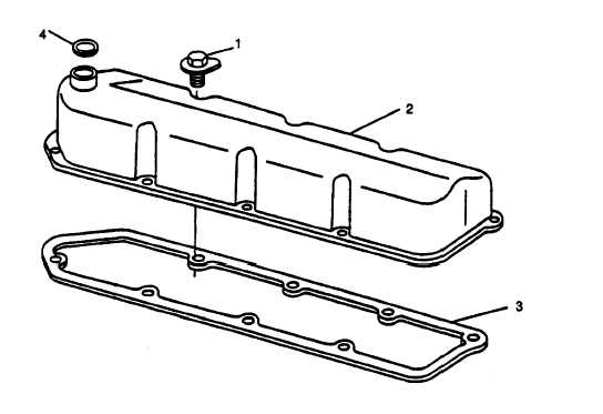
FIGURE 3-94. Valve Cover
3-32. INTAKE AND EXHAUST VALVE CHECKS.
3-32.1. Check and Adjust Valve Clearance.
NOTE
Valve clearance can be checked with engine cold or warm.
a.
Remove valve cover with ventilator tube, refer to paragraph 3-31.1.
b.
Remove plastic plugs in engine timing holes.
c.
Using center bolt on harmonic balancer, rotate crankshaft clockwise until No. 1 piston is at TDC on compression
stroke.
NOTE
If rocker arms for No. 1 cylinder are loose, engine is at No. 1 TDC compression.
d.
Valve clearance (rocker arm-to valve tip) is:
(1)
Intake Valve ......................................................... 0.014 in. (0.35 mm)
(2)
Exhaust Valve ......................................................0.018 in. (0.45 mm)
e.
If valve clearance is not within specification, refer to following steps and adjust valve clearance.
NOTE
Excessive valve clearance indicates wear on camshaft and/or cam followers.
NOTE
Firing order is 1-3-4-2. Intake and exhaust valve locations are designated I and E in FIGURE 3-95.
U.S. GOVERNMENT PRINTING OFFICE: 1996-755-119-/40019
Change 2 3-130
|
|