ARMY TM 9-2815-255-24
AIR FORCE TO 38G1-95-2
MARINE CORPS TM 2815-24/4
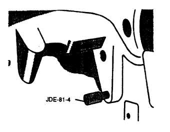
FIGURE 3-97. Installing Timing Pin
c.
Set rocker arm-to-valve tip clearance to 0.00 inch (0.00 mm) by turning adjustment nut clockwise until pushrod
cannot be turned by hand for No. 1 and 3 exhaust and No. 1 and 2 intake valves, refer to FIGURE 3-96.
NOTE
Refer to FIGURE 3-95 for engine valve locations.
d.
Place dial indicator tip on top of valve spring cap or rotator. Preload indicator tip and set dial at 0.00 inch (0.00
mm).
e.
Remove timing pin from flywheel and manually turn engine in running direction one full revolution (360 degrees).
f.
Observe dial indicator reading as valve is moved to full open. Record readings and compare with specifications
given below.
Intake Valves..........................................................................................0.455 to 0.487 in. (11.56 to 12.37 mm)
Wear Tolerance...........................................................................................................0.438 in. (11.13 mm)
Exhaust Valves.......................................................................................0.444 to 0.477 in. (11.28 to 12.12 mm)
Wear Tolerance...........................................................................................................0.427 in. (10.85 mm)
g.
Measure all remaining valves in accordance with steps d, e, and f and record readings.
h.
If valve lift is not within specification, remove and inspect entire valve train and camshaft.
i.
If valve lift is within specification, adjust valves to specified clearance, as outlined in paragraph 3-32.1. and
continue measuring lift on remaining valves.
CAUTION
Rocker arm shaft bolts must be loosened and tightened a little bit at a time to avoid warping
shaft.
j.
Rotate engine clockwise and observe No. 4 pushrods. When both pushrods can be rotated freely, engine is on
compression stroke. Continue to rotate engine until timing pin (JDE-81-4) can be installed in flywheel.
k.
Set rocker arm-to-valve tip clearance to 0.00 inch (0.00 mm) for No. 2 and 4 exhaust and No. 3 and 4 intake
valves.
3-132
|
|