ARMY TM 9-2815-255-24
AIR FORCE TO 38G1-95-2
MARINE CORPS TM 2815-24/4
3-34.7. Installation.
a.
Perform procedures in paragraph 3-34.6.
b.
Place new cylinder head gasket (3, FIGURE 3-99) on cylinder block. Do not use sealant; install dry.
CAUTION
Without guide studs, viton O-ring seal bonded In cylinder head gaskets (at rocker arm lube oil
passage) could become damaged n cylinder head requires repositioning on engine block to align
capscrew hole.
c.
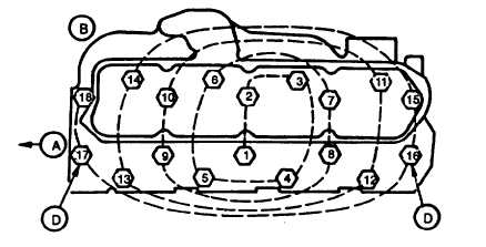
Install two guide studs in cylinder block (for piloting cylinder head) at locating holes 16 and 17 shown in FIGURE
3-104.
FIGURE 3-104. Cylinder Head Capscrew Tightening Sequence
d.
Using a lifting device, position cylinder head (2, FIGURE 3-99) over guide studs and lower into place on cylinder
block.
e.
Dip entire capscrew (1) in clean engine lubricating oil (MIL-L-2104). Remove excess oil from screw.
f.
Remove guide studs. Install eighteen cylinder head capscrews (1).
g.
Tighten capscrews (1) in sequence shown in FIGURE 3-104 to torque specified below, beginning with No. 1
capscrew. Complete each step on all capscrews before proceeding to next step.
(1)
Step 1 - Tighten all capscrews to 75 ft-lbs (100 Nm).
(2)
Step 2 - Tighten all capscrews to 110 ft-lbs (150 Nm).
(3)
Step 3 - Wait 5 minutes and verify 110 ft-lbs (150 Nm).
h.
After tightening capscrews (in proper sequence) to 110 ft-lbs (150 Nm), follow the steps below for each
capscrew in same sequence as outlined in step g.
(1)
Make a mark on socket and make a second mark 116 turn (60 10 degrees) counterclockwise from the
first.
(2)
Make a mark on cylinder head next to each capscrew.
(3)
Place socket on capscrew so that first mark aligns with mark on cylinder head.
(4)
Tighten (in sequence) all caps crews until second mark on socket aligns with mark on cylinder head.
3-148
|
|