ARMY TM 9-2815-255-24
AIR FORCE TO 38G1-95-2
MARINE CORPS TM 2815-24/4
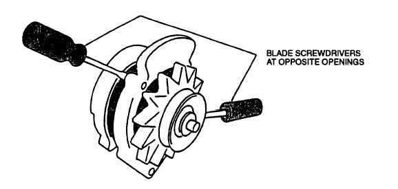
FIGURE 3-7. Stator and Rear Housing Separation
e.
Inspect other components for damage such as broken terminals or insulation, discoloration, stripped threads, and
other obvious damage.
f.
Replace damaged components as necessary.
311.5. Testing.
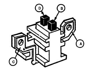
a.
Set multimeter for ohms and check brush assembly (refer to FIGURE 3-8) for continuity between mount A and
brush B, and mount C and brush D. Check for open circuits between mount A and mount C, mount A and brush
D, mount C and brush B, and brush B and brush D. Replace brush assembly if indications are other than stated.
FIGURE 3-8. Testing Brush Assembly
b.
Set multimeter for ohms and check diode-trio assembly (refer to FIGURE 39) by noting multimeter indications
between D+ stud and each of stator terminals. Reverse multimeter leads, repeat checks and note indications. if
readings are the same in both directions for any diode, replace entire diode-trio assembly. A good diode will
show a high indication in one direction and a low indication in the other.
3-30
|
|