ARMY TM 9-2815-255-24
AIR FORCE TO 38G1-95-2
MARINE CORPS TM 2815-24/4
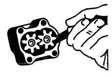
FIGURE 3-37. Measuring Oil Pump Radial Clearance
3-21.3. Installation.
a.
Install new preformed packing (8, FIGURE 335) on oil pump intake tube (7) cover.
b.
Install outlet tube (3) with new preformed packing (4).
c.
Install pump (11) with oil pump intake tube (7) on front plate and secure with two bolts (5), two bolts (9), and
flatwashers (6 and 10). Tighten bolts to 35 ft-lbs (47 Nm).
d.
Rotate oil pump shaft by hand to ensure it turns freely.
e.
Install drive gear (2) and nut (1). Tighten nut to 55 ft-lbs (75 Nm).
f.
Stake nut (1) to shaft by applying three center punch marks.
g.
Install oil pan, refer to paragraph 3-20.3.
3-21.4. Test.
a.
Attach pressure gage at pressure port shown on FIGURE 3-38.
CAUTION
Before checking the oil pressure, warm up engine to allow the lubricating oil to reach operating
temperature or high oil pressure readings will occur.
b.
At 850 rpm engine speed and 220°F (102°C) operating temperature, gage should show a minimum pressure of
15 psi (103 kPa).
c.
At rated speed (1800 to 2500 rpm) and 220°F (1050C) operating temperature, gage should show a pressure
between 40 and 70 psi (277 to 483 kPa).
3-68
|
|