ARMY TM 9-2815-256-24
AIR FORCE TO 38G1-96-2
MARINE CORPS TM 2815-24/5
c.
Measure camshaft thrust plate clearance as follows:
NOTE
Thrust plate clearance determines camshaft end play.
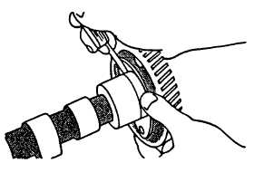
(1) Check thrust plate clearance using a feeler gage, refer to FIGURE 3-130.
(2) New part clearance is 0.003 to 0.009 inch (0.08 to 0.23 mm). Maximum allowable clearance is 0.015 inch
(0.38 mm). Replace parts as necessary.
FIGURE 3-130. Measuring Thrust Plate Clearance
d.
Measure camshaft journals as follows:
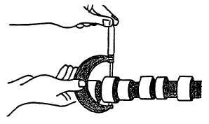
(1) Use a micrometer to take measurements, refer to FIGURE 3-131.
(2) New camshaft journal diameter is 2.200 to 2.201 inches (55.87 to 55.90 mm). Maximum wear tolerance is
0.001 inch (0.025 mm).
(3) If a camshaft journal diameter is less than 2.199 inches (55.85 mm), install a new camshaft.
(4) Measure camshaft bearing bore diameter in cylinder block; 2.204 to 2.205 inches (55.98 to 56.01 mm).
Maximum clearance between bore and camshaft journal; 0.007 inch (0.18 mm).
FIGURE 3-131. Measuring Camshaft Journals
e.
Measure camshaft lobe height as follows:
(1) Measure each camshaft lobe at highest point and at narrowest point, refer to FIGURE 3-132. Subtract
narrowest dimension from highest dimension to find camshaft lobe height. If height is not correct on any
lobe, install a new camshaft.
3-171
|
|