ARMY TM 9-2815-25624
AIR FORCE TO 38G1-96-2
MARINE CORPS TM 2815-24/5
(2) Intake lobe should be 0.273 to 0.292 inch (6.93 to 7.42 mm), with a minimum acceptable lobe height of 0.263
inch (6.68 mm).
(3) Exhaust lobe should be 0.266 to 0.286 inch (6.76 to 7.26 mm), with a minimum acceptable lobe height of
0.256 inch (6.50 mm)
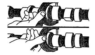
FIGURE 3-132. Measuring Camshaft Lobe Sight
f.
Inspect cam followers in accordance with instructions in paragraph 3-34.4.
3-40.3. Installation.
a.
Install gear (5, FIGURE 3-128) as follows:
(1)
Install key (6) in camshaft.
(2)
Install gear (5) with timing mark facing away from camshaft (3), aligning slot in gear with key (6).
(3)
Using a tubular driver, press gear (5) on camshaft (3) until gear is flush with shoulder on camshaft.
b.
Coat camshaft lobes and cam followers (2) with a general purpose grease (630AA).
c.
Make sure engine is at TDC, (No. 1 piston on compression stroke) with timing pin engaged in flywheel.
CAUTION
Do not allow camshaft lobes to drag on engine block honed bore surfaces while installing
camshaft. Machine surfaces may become scratched or scored. Revolve camshaft during
installation to avoid obstruction in any bore.
d.
Put clean engine lubricating oil (MIL-L-2104) on camshaft bearing journals.
e.
Install camshaft (3) and thrust plate (4) in engine block.
f.
Install two capscrews (1) and tighten to 35 ft-lbs (47 Nm).
g.
Time camshaft as follows:
NOTE
If not removed, remove upper idler gear, refer to paragraph 3-41.1.
(1) With timing tool (JD-254) resting on nose of crankshaft, turn camshaft (3) until timing mark aligns with center
of camshaft gear (5), refer to FIGURE 3-133.
(2) Check injection pump gear timing with timing tool (JD-254). Timing mark with 6" beside it, must align with
center of injection pump gear.
3-172
|
|