ARMY TM 9-2815-256-24
AIR FORCE TO 38G1-96-2
MARINE CORPS TM 2815-24/5
NOTE
When inspecting crankshaft for cracks, a method (such as the Fluorescent Magnetic Particle Method)
must be used that is capable of detecting minute cracks that are not visible to the eye. This method
magnetizes the crank, employing magnetic particles which are fluorescent and glow under black light.
Replace crankshaft if cracks are found. The crankshaft must be demagnetized after the test.
(4)
Check each journal for evidence of excessive overheating or discoloration. If either condition exists,
replace crankshaft since heat treatment has probably been destroyed.
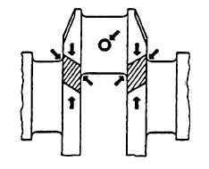
FIGURE 3-138. Critical Areas of Crankshaft Load Stress
d.
Measure assembled ID of bearings and OD of crankshaft journals as follows:
(1)
With crankshaft out of engine block, install main bearing inserts and caps (be sure inserts are installed
correctly).
(2)
Tighten main bearing capscrews to 85 ft-lbs (115 Nm).
(3)
Measure ID of all bearings with an inside micrometer. ID of assembled insert should be 3.125 to 3.127
inches (79.39 to 79.44 mm).
(4)
Measure OD of all respective crankshaft journals at several points around journal. OD of main bearing
journal should be 3.123 to 3.124 inches (79.34 to 79.36 mm).
NOTE
If engine has previously had a major overhaul and undersized bearing inserts were used, above
listed ID and OD dimensions may not be the same as those recorded. However, oil clearance should
be within specifications. Oil clearance is 0.0012 to 0.004 inch (0.030 to 0.10 mm). The maximum
serviceable clearance is 0.006 inch (0.15 mm).
(5)
Use crankshaft journal OD measurements to determine if journal is out-of-round or tapered. Journal out-
of-roundness wear limit is 0.003 inch (0.08 mm). Journal taper-per-inch of journal length wear limit is
0.0001 inch (0.025 mm)
(6)
If journals are tapered, out-of-round, scored, or damaged, crankshaft should be ground. Refer to
paragraph 3-43.3. Proper undersize bearings should be installed after grinding.
e.
Measure main thrust journal width and thrust bearing width, refer to FIGURE 3-139, as follows:
(1)
Measure width of main thrust journal with an inside micrometer.
(2)
New main thrust journal width is 1.531 to 1.535 inches (38.90 to 39.00 mm).
(3)
If width is not within specification, recondition crankshaft and install an oversize thrust washer set. If width
is correct, measure main thrust bearing width.
3-184
|
|