ARMY TM 9-2815-256-24
AIR FORCE TO 38G1-962
MARINE CORPS TM 2815-24/5
(4)
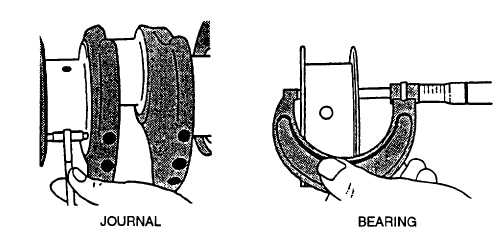
Measure width of thrust bearing using an outside micrometer.
FIGURE 3-139. Measuring Main Thrust Journal and Thrust Bearing Width
(5)
New main thrust bearing width (standard size) is 1.528 to 1.530 inches (38.80 to 38.85 mm)
(6)
New main thrust bearing clearance (thrust journal width minus thrust bearing width) is 0.002 to 0.008 inch
(0.05 to 0.20 mm).
(7)
Maximum allowable thrust bearing clearance is 0.015 inch (0.38 mm). Oversize thrust washer sets have
thrust washers that are 0.007 inch (0.18 mm) oversize.
f.
Measure assembled ID of main bearing caps as follows:
(1)
Remove bearing inserts from caps and engine block. Keep inserts in correct order if they are to be reused.
(2)
Clean caps in solvent and dry with compressed air.
(3)
Inspect caps for serviceability. Small burrs or nicks on flat surfaces may be removed with a file. Use a
medium-grit polishing cloth to dress up curved bearing surfaces.
(4)
Install bearing caps in engine block. Tighten capscrews to 85 ft-lbs (115 Nm).
(5)
Measure ID of bore without bearings. Main bearing bore ID without bearings should be 3.325 to 3.326
inches (84.45 to 84.48 mm).
(6)
If bearing caps are damaged or bore is not within specification, replace cap and bore to specification.
CAUTION
Main bearing cap line boring should be done only by experienced personnel on equipment capable of
maintaining the bore specifications. Make sure that dimension from centerline of core-to-top deck of
engine block does not exceed 11.889 to 11.894 inches (301.98 to 302.11 mm)
NOTE
Replacement bearing caps are supplied with bearing bore unfinished.
g.
Inspect piston cooling orifices as follows:
(1)
Inspect each cooling orifice to make sure it is not plugged or damaged.
(2)
Use a soft wire and compressed air to clean orifice. Replace, if condition is questionable.
3-185
|
|


