ARMY TM 9-2815-257-24
AIR FORCE TO 38G1-128-2
MARINE CORPS TM 10155A/2815-24/3
5-15
5-8. BALANCER SHAFT ASSEMBLY MAINTENANCE - cont.
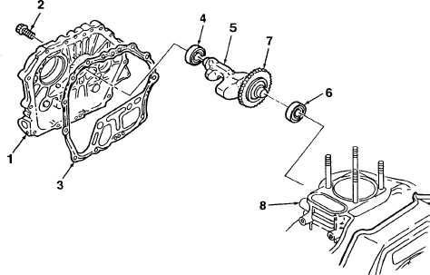
Figure 5-7. Balancer Shaft Assembly Removal
D. INSTALLATION.
1.
If removed, install bearings (4, 6, Figure 5-7).
2.
Carefully insert assembled balancer shaft (5) and
gear (7) into cylinder block (8). Align match-
marks on balancer gear and crankshaft gear, then
press balancer shaft (5) into bearing (6).
3.
Apply grease to lips of crankshaft oil seal
(located in crankcase cover (1)).
4.
Apply oil to crankshaft and camshaft. Make sure
that oil pump drive gears are properly engaged.
5.
Mate cover gasket (3) to cylinder block (8).
6.
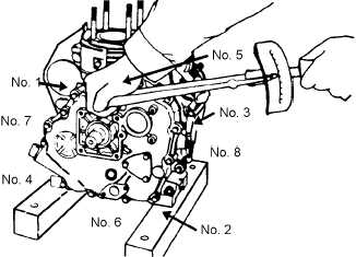
Mate crankcase cover (1) to cylinder block (8)
and secure using fifteen screws (2). Tighten
screws in criss-cross sequence as shown in Figure
5-8. Torque all screws to 14.5 to 16.6 ft-lbs. (200
to 230 kg-cm).
7.
Service engine oil (Para. 3-6).
Figure 5-8. Crankcase Cover Bolt
Tightening Sequence
|
|