ARMY TM 9-2815-259-24
AIR FORCE TO 38G1-125-2
MARINE CORPS 09249A/09246A-24
5-33
(20) Install seal (87, Figure 5-1) into groove on hydraulic head (48).
(21) Position cam ring (88) on rotor assembly (86) with directional arrow facing counterclockwise
when viewed from above.
(22) Carefully slide hydraulic head assembly (87) over rotor.
(23) Install transfer pump end cap seal (85). Insure that transfer pump end cap seal is pushed
completely down into groove.
(24) Install rotor retainers (84). Align cutouts in rotor retainers with hole in hydraulic head.
(25) Install liner locating ring (83) with opening in liner locating ring 90° (1/4 revolution) from rotor
retainer (84) ends.
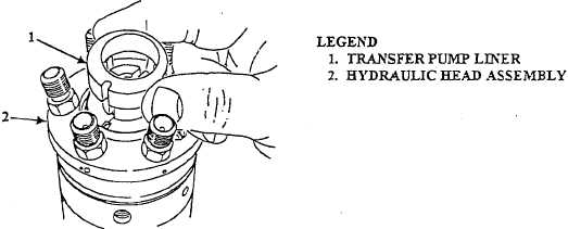
(26) Install transfer pump liner (1, Figure 5-41) with notch aligned with hole in hydraulic head
assembly (2).
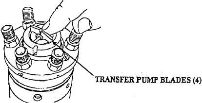
(27) Install transfer pump blades (Figure 5-42) and springs one pair at a time.
FIGURE 5-41. TRANSFER PUMP LINER INSTALLATION (TYPICAL)
FIGURE 5-42. TRANSFER PUMP BLADE INSTALLATION (TYPICAL).
|
|