ARMY TM 9-2815-259-24
AIR FORCE TO 38G1-125-2
MARINE CORPS 09249A/09246A-24
5-34
(28) Install sleeve seal (78, Figure 5-1) into groove in transfer pump regulator assembly (74). Ensure
that sleeve seal is seated completely.
(29) Position piston (77) in transfer pump regulating assembly (74) with open end of piston facing
outward.
NOTE
Adjusting screw is fragile. Do not exert excessive downward force on hex
wrench while installing adjusting screw. Failure to comply could result in
damage to adjusting screw.
(30) Install spring and adjusting screw (76, 75) into transfer pump regulating assembly (74). Tighten
adjusting screw until adjusting screw is 1-2 threads below flush with end of sleeve of transfer
pump regulator housing.
(31) Install inlet filter screen (73) on transfer pump regulator assembly (74).
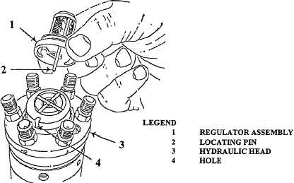
(32) Install regulator assembly (1, Figure 5-43) on hydraulic head (3) by aligning locating pin (2) with
hole (4).
FIGURE 5-43. REGULATOR ASSEMBLY INSTALLATION (TYPICAL).
(33) Apply thin coating of grease (Appendix E) to beveled surface on inside of transfer pump end cap
(72, Figure 5-1) and to threads of transfer pump end cap.
(34) Position transfer pump end cap (72) on hydraulic head assembly. Rotate transfer pump end cap
counterclockwise until “click” is heard, then rotate transfer pump end cap clockwise until hand
tight.
(35) Position governor arm (55) in fuel injection pump housing with linkage hook (56) hanging over
side of fuel injection pump housing.
|
|