ARMY TM 9-2815-260-24
AIR FORCE TO 38G1-126-2
MARINE CORPS TM 09244A/09245A-24
4-19
(b) Replace entire rectifier bridge assembly if readings are the same in both directions for any
diode. A good diode will have a high indication in one direction and a low indication in the
other.
(16)
Check or replace negative diodes as follows:
(a) Set multimeter for ohms and connect positive test probe of ohmmeter to positive heat sink (C)
and negative test probe to leads (B) of diodes (refer to Figure 4-6). Meter must show
continuity. Reverse leads, repeat check and note indications.
(b) Replace entire rectifier bridge assembly if readings are the same in both directions for any
diode. A good diode will have a high indication in one direction and a low indication in the
other.
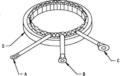
FIGURE 4-7. TESTING STATOR WINDINGS
(17)
Check or replace stator as follows:
(a)
Set multimeter for ohms and check stator (refer to Figure 4-7) for open circuits between
point D (lamination) and each terminal A, B, and C.
(b)
If continuity is noted between lamination and any terminal, stator is defective and must be
replaced.
(c)
Set multimeter for ohms and check stator windings (refer to Figure 4-7) for continuity
between terminals A-B, A-C, and B-C.
(d)
If open, replace stator.
|
|


