ARMY TM 9-2815-260-24
AIR FORCE TO 38G1-126-2
MARINE CORPS TM 09244A/09245A-24
4-20
(18)
Check/replace rotor assembly.
(a)
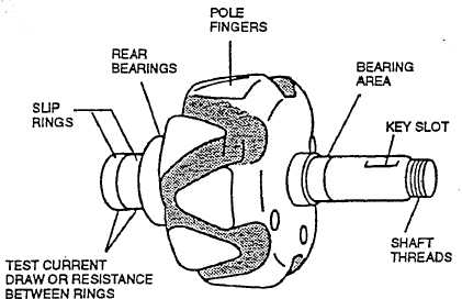
Set multimeter for ohms, clean sliprings with solvent, and check rotor assembly (refer to
Figure 4-8) for 9.0 to 14.0 ohms indication between slip rings.
(b)
Check that open circuits are indicated between pole fingers and each slip ring.
(c)
Replace entire rotor assembly if indications are other than stated in (a) and (b) above.
FIGURE 4-8. TESTING ROTOR
c.
Assembly.
(1)
Install bearing (4, Figure 4-2) on rotor assembly (3).
(2)
Install bearing plate, bearing (2) and drive end housing (1) on rotor assembly (3).
(3)
Install bearing plate bolts (16), through front of drive end housing (1); alternately tighten bolts
which pull bearing (2) into drive end housing (1).
(4)
Install splash shield (7) on to service slip ring end of rotor assembly (3).
(5)
Connect tagged stator (9) leads to rectifier (6).
(6)
Install bolts (16) and rectifier (6) on slip ring end housing (5).
(7)
Align drive end housing (1) with slip ring end housing (5) and tap into position using soft face
mallet.
|
|