TM 9-2920-243-34
MACK Model ENDT 673 engines.
However, the pinion housing is positioned
differently for certain engine application.
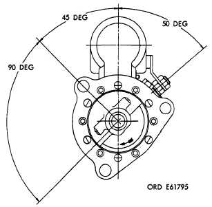
Figure 3-40 illustrates position for LDS-
465-1, LDS-465-lA and MACK Model
ENDT 673 engine applications, figure 3-
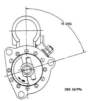
41 illustrates position for LD-465-1, LD-
465.lC and LDT-465-lC engine ap-
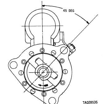
plications, and figure 3-42 illustrates
position for LDS-465-2 engine ap-
plications.
Figure 3-42. Pinion housing position for LDS-465-2 engine
application.
3-25. Installation of Solenoid Relay Assembly
a. Place relay assembly (C, fig. 3-4) on field
Figure 3-40. Pinion housing position for LDS-456-1,
LDS-465-1A and MACK Model ENDT 673 engine applications.
Figure 3-41 Pinion housing position for LD-465-1, LD-465-lC
and LDT-465-1C engine applications.
ring and guide shaft, and insert assembly (fig. 3-
9) through seal in relay cover. Make certain shaft
enters plunger so threaded end of shaft is alined
with hole in plunger.
b. Insert shaft adjusting tool (A, fig. 3-4) and
engage end of tool with end of adjusting shaft.
Turn tool clockwise to engage plunger with shaft
and insert assembly (fig. 3-9). Turn tool eight
complete turns.
c. Move relay so that it alines with mounting
holes in field ring and secure with two hex-head
bolts (A, fig. 3-3).
d. Using shaft adjusting tool (A, fig. 3-4) turn
adjusting shaft clock wise eight additional turns.
e. Apply 24 volts direct current across ter-
minals 1 and 3.
NOTE
Terminals are numbered with raised
numerals on the relay cover.
CAUTION
Never leave relay energized any longer
than necessary to check clearance. Also,
never make adjustment when relay is
energized.
f. Refer to figure 3-43. Gently push drive
assembly back against arm and measure
3-18
|
|