
| Tweet |

Custom Search
|
|

|
||
 ARMY TM 9-6115-666-13&P
AIR FORCE TO 35C2-3-505-1
4.16. INDICATOR LIGHT MAINTENANCE (cntinued).
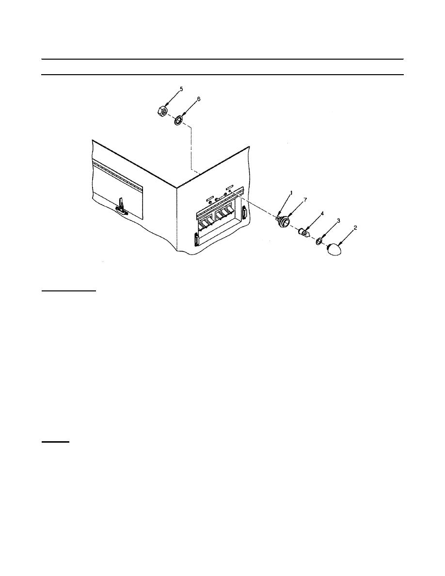
Figure 4-10. Indicator Light Replacement.
INSTALLATION
1. Remove mounting nut (5), and internal tooth lock washer (6) from new indicator housing (7).
2. Insert indicator housing (7) through switch box panel.
3. Install new internal tooth lock washer (6) on indicator housing.
4. Install mounting nut (5) on indicator housing.
5. Solder wires to the applicable terminals and remove tags.
6. Install lens (2), O-ring (3), and lamp (4).
7. Position panel covers and secure using six screws.
8. Install switch box cover and secure with strap assembly.
REPAIR
Repair is limited to removal and installation of new indicator lamp housing.
4-27
|
||
|
||


