
| Tweet |

Custom Search
|
|

|
||
 TM 9-8000
c. Combustion Chambers (Fig. 3-6). The
cylinder head seals the end of the cylinder. This
serves to provide a combustion chamber for the
ignition of the mixture and to hold the expansive
forces of the burning gases so that they may act on
the piston. There is a threaded hole to position
the spark plug in the combustion chamber on
gasoline engines. On diesel engines there is a
similar arrangement to position the fuel injector.
d. Valves and Ports (Fig. 3-7). The cylinder
head on overhead valve configurations supports
the valves and has the ports cast into it. The
cylinder head on overhead camshaft configura-
tions also supports the camshaft.
e.
Cooling.
(1) Cylinder heads on air-cooled configu-
rations (A, fig. 3-8) have fins cast into their outer
surfaces.
(2) Cylinder heads on liquid-cooled con-
figurations (B, fig. 3-8) have passages for
coolant flow cast into them.
f.
Sealing.
(1) Cylinder heads on air-cooled configu-
rations (A, fig. 3-9) are sealed to the tops of the
cylinders by soft metal rings. The lubrication
system usually feeds oil to the heads through the
push rods.
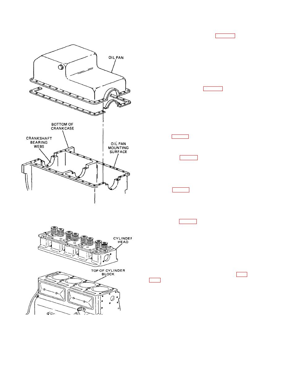
Figure 3-4. Engine Crankcase.
(2) Cylinder heads on liquid-cooled con-
figurations (B, fig. 3-9) are sealed to the
cylinder block by the head gasket. The head
gasket usually is made of two sheets of soft steel
that sandwich a layer of asbestos. Steel rings are
used to line the cylinder openings. They are to
hold the tremendous pressures created on the
power stroke. Holes are cut in the gasket to mate
the coolant and lubrication feed holes between the
cylinder block and the cylinder head.
3-3.
Cylinders - Air-Cooled Engines (Fig.
separate from the crankcase. They usually are
made of forged steel. This material is most
suitable for cylinders because of its excellent
wearing qualities, and its ability to withstand the
high temperatures that air-cooled cylinders do
obtain. The cylinders have rows of deep fins cast
into them to dissipate engine heat. The cylinders
TA233354
Figure 3-5. Typical Cylinder Head Installation.
3-4
|
||
|
||


