| Tweet |

Custom Search
|
|

|
||
 TM 9-8000
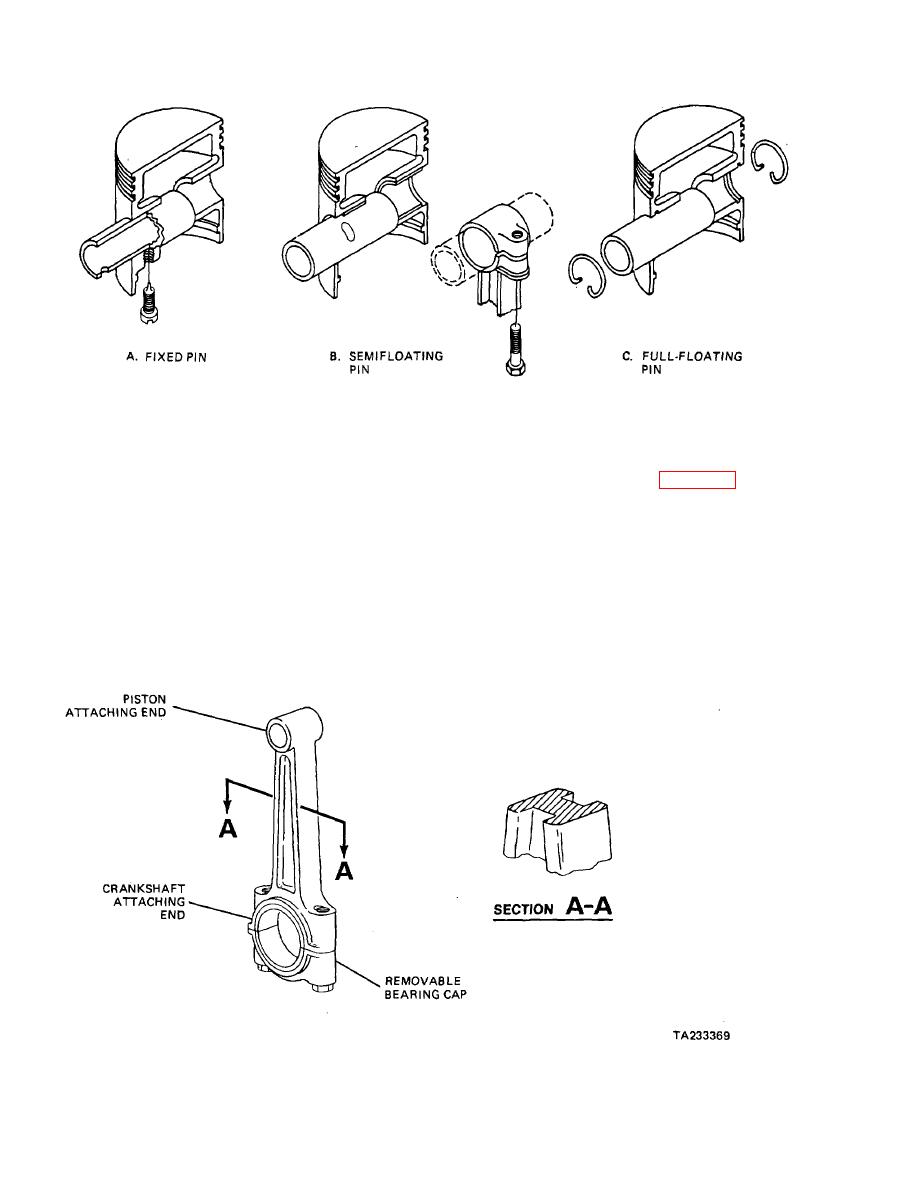
Figure 3-32. Piston Pin Configurations.
that it is made with offset throws. The weight of the
heavy crankshaft construction and sufficient support
throws tend to make the crankshaft rotate elliptically.
along its length by bearings.
This Is aggravated further by the weight of the piston and
(3) Torsional Vibration (Fig. 3-37). Torsional vibration
the rod. To eliminate the problem, weights are positioned
along the crankshaft. One weight is placed 180 degrees
occurs when the crankshaft twists because of the power
away from each throw. They are called counterweights
stroke thrusts. It Is particularly noticeable on engines with
and are usually part of the crankshaft, but may be
long crankshafts, such as In-line engines. It is a major
separate bolt-on items on small engines.
reason why in-line, eight-cylinder engines are no longer
produced. The vibration is caused by the cylin- ders
(2) Vibration Due to Deflection. The crank-
furthest from the crankshaft output. As these cylinders
shaft will have a tendency to bend slightly when
apply thrust to the crankshaft, it twists, and as the thrust
subjected to the tremendous thrust from the piston. This
decreases, the crankshaft unwinds. The twisting and
deflection of the rotating member will cause a vibration.
unwinding of the crankshaft produces a vibration. The
This
vibration
is
minimized
by
use of a
Figure 3-33. Connecting Rod Construction.
3-19
|
||
 |
||