
| Tweet |

Custom Search
|
|

|
||
 TM 9-8000
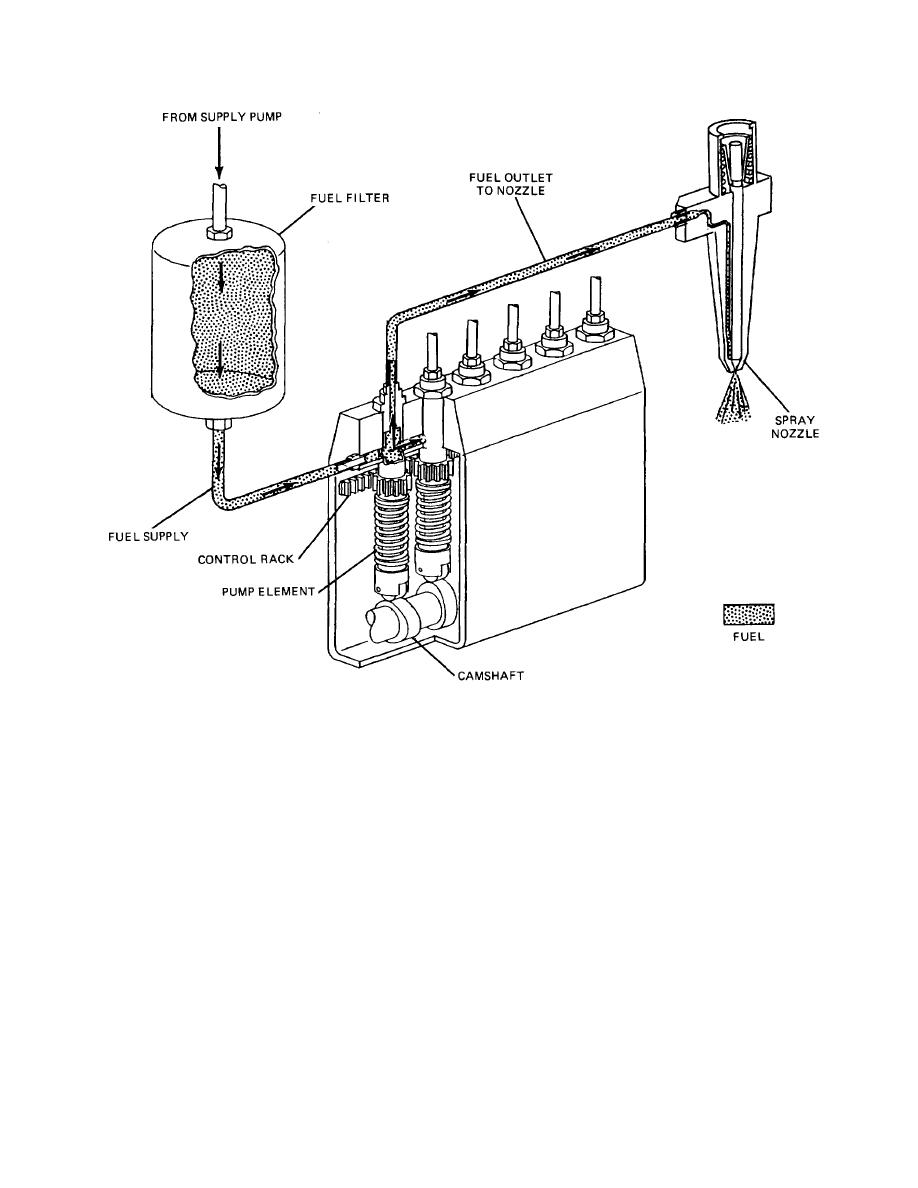
Figure 5-6. General System Operation.
(2) Excess fuel flows from the injection pump
the cavity is forced out of the pump and to its respective
through the relief valve and back to the fuel tank. The
injector.
relief valve usually is adjusted to open at approximately
15 psi (103.4 kPa).
(4) The pump plunger has a rectangular slot cut into
it that leads from the top face, down the side, and finally
(3) The pumps consist of a finely fitted plunger that
connecting to a helical shaped cavity that is called the
is actuated by the camshaft against the force of the
bypass helix. In operation, the slot will allow fuel to pass
plunger spring. The bore that the plunger rides in has
to the bypass helix. As the bypass helix passes over the
two passages machined into it. One of these passages
spill port, it will allow a portion of the fuel charge to
is the delivery port, through which the pump is filled. The
bypass back to the fuel tank rather than being injected
other passage is the spill port, through which excess fuel
into the engine cylinder. The outer pump sleeve is made
is discharged. When the plunger is fully in its return
to rotate and has gear teeth around its outer diameter. A
position, fuel flows into the pump cavity through the
horizontal toothed rack meshes with these gear teeth to
uncovered delivery port and out of the pump cavity
rotate the sleeve without any plunger rotation. By
through the uncovered spill port. The pump cavity
moving the rack back and forth, the outer pump sleeve is
always is kept full as the fuel flows through. The plunger
rotated, moving the delivery and spill ports in relation to
moves up in its bore as it is actuated by the camshaft,
the bypass helix on the pump plunger. This enables the
sealing the ports.
The fuel that is
trapped in
volume of fuel injected to the
TA233443
5-9
|
||
|
||


