| Tweet |

Custom Search
|
|

|
||
 TM 9-8000
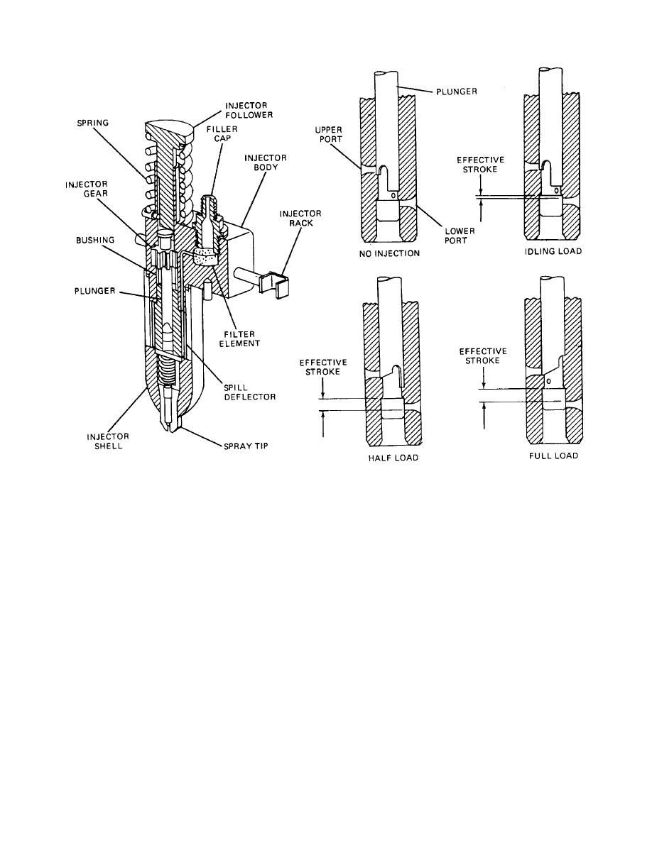
Figure 5-15. Unit Injector Operation
in the cylinder head with their spray nozzles protruding
at different heights. The plunger operates up and down
into the combustion chamber. A clamp, bolted to the
in the bushing bore.
cylinder head and fitting into a machined recess in each
side of the injector, holds the injector in place in a water-
(3) The plunger is actuated by a camshaft that
cooled copper tube that passes through the cylinder
is built right into the engine. The operation takes place
head. The tapered lower end of the injector seats in the
through a rocker arm and a push rod. The push rod has
copper tube, forming a tight seal to withstand the high
a roller-type cam follower and is spring loaded to prevent
pressures inside the cylinder. The injector operates as
component damage in the event of injector nozzle
follows:
clogging.
The plunger is situated under a follower.
This follower is spring loaded to make it follow the
(1) Fuel is supplied to the injector through the
camshaft.
filter cap. After passing through the fine grained filter
element in the inlet passage, the fuel fills the annular-
(4) The plunger can be rotated in operation
shaped supply chamber that is created between the
around its axis by the gear, which is meshed to the
bushing and the spill deflector.
control rack.
Each injector rack is connected by an
easily detachable joint to a lever on a common control
(2)
The bushing bore is connected to the
tube which, in turn, is linked to the governor and the
throttle.
fuel supply by two funnel-shaped ports, one on each side
TA233451
5-20
|
||
 |
||