| Tweet |

Custom Search
|
|

|
||
 TM 9-8000
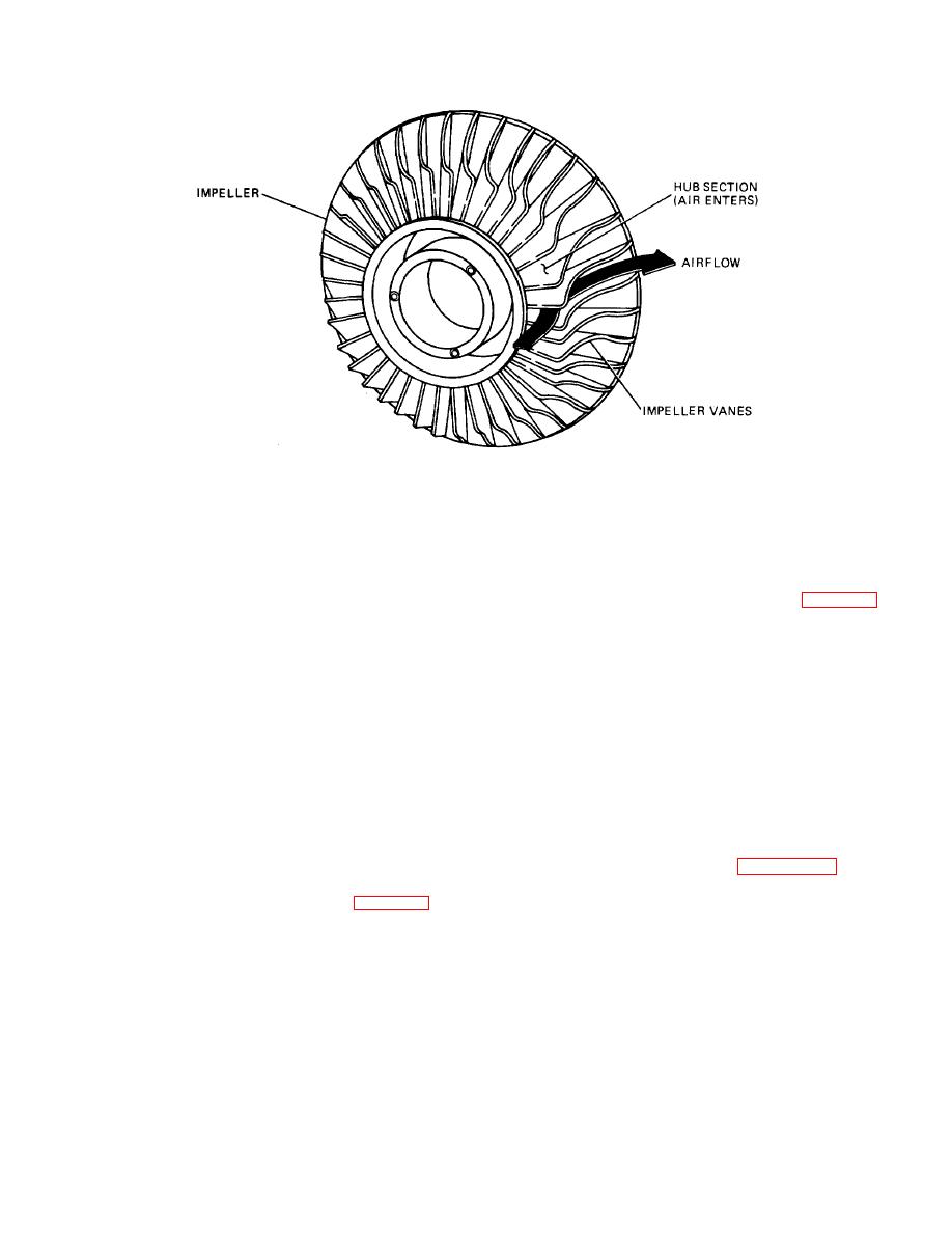
Figure 10-8. Centrifugal Compressor
b. Low specific fuel consumption.
effect. The gases then are exhausted at the top of the
turbine, parallel to the axis of rotation. Despite its
c. Lowered exhaust temperature.
simplistic design and durability, the radial inflow turbine
generally is limited to use in smaller engines.
Basically, the only disadvantage to this system is the
additional weight of the unit to the vehicle.
b. Axial Flow. The axial flow turbine (fig. 10-13) is
composed of two main elements: a set of stationary
vanes and a turbine rotor or rotors. The axial flow
10-12. Turbines. The turbine is designed to extract the
turbine rotors are categorized into two basic types:
kinetic energy (energy due to motion) from the
impulse and reaction. The modern turbine consists of a
expanding gases that flow from the combustion
combination of these two called the impulse-reaction
chamber. This kinetic energy then is converted into shaft
turbine. Each is discussed below. As the name implies,
horsepower to drive the compressor and engine
the axial flow turbine wheel extracts kinetic energy from
accessories. Most of the energy obtained from the
the moving gases that flow in a relatively straight line,
products of combustion (approximately 75 percent) is
parallel to the axis of rotation. The turbine wheel is used
used to drive the compressor. The remaining 25 percent
as the rotating element. Stationary vanes are used to
is utilized to power additional components such as oiling
deliver the gas to the next stage in the most efficient way
system and hydraulic systems.
Additional power
possible.
turbines are used to extract residual energy from the
moving gases to provide vehicular power. Turbines can
(1) Impulse Turbine. The construction of the
be divided into two basic types: radial inflow and axial
impulse turbine is illustrated in figure 10-14. In this
flow.
configuration the area of the inlet and exit of the turbine
blades are made equal. Thus, the velocity of the gas
a. Radial Inflow. This type of turbine (fig. 10-12) is
entering the blade is equal to the exiting velocity (minus
similar to the centrifugal compressor in design and
frictional losses). The blades are designed in such a way
construction. Radial inflow operates as the inlet gases
that the high-velocity gases concentrate their energies on
pass through openings that direct the gases onto the
the center of the blade. The gases then bounce off the
blades at the base of the compressor. The gas then acts
TA233510
against the blades of the turbine to produce the rotational
10-9
|
||
 |
||