
| Tweet |

Custom Search
|
|

|
||
 TM 9-8000
through the fine winding on the control unit to pull the
A simple way of accomplishing this is shown in figure 13-
contact points apart. When this happens, the resistance
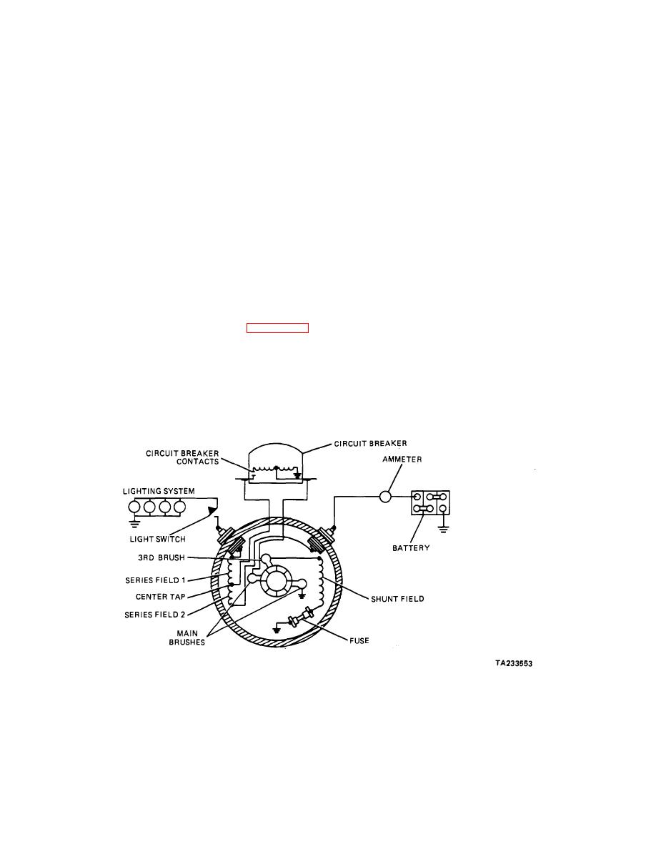
14. A resistance is mounted on the back of the lighting
across the contacts is connected in series with the field
switch and connected in series with the field. When the
winding to lower the field strength and, consequently, to
lights are off, the generator output current is limited by
reduce the generator voltage and the current output.
the resistance in the field circuit. When the lights are
When the voltage is lowered sufficiently, spring tension
turned on, the resistance is shorted so that the generator
will close the contact points and the higher charging rate
delivers full current to take care of the additional lighting
will be restored.
circuit load. This is just a two-step arbitrary system of
(3) When there is sufficient electrical load (such as
regulation, however, that will not meet the varied load
lights, radio, or heater) to require a higher generator
requirements of normal vehicle operation.
output, the contact points will close, because the load will
lower the generator voltage and the generator will
b. Step-Voltage Control.
produce maximum output for the selected position of the
third brush and the speed at which it is driven.
(1) The purpose of step-voltage control is to increase
or decrease the output of a third- brush generator in
c. Vibrating Regulator Control. A vibrating regulator
accordance with the requirements of the battery and the
(para 13-13) also can be used with a third-brush
connected electrical load.
It is really a two-stage
generator. Such a regulator is controlled by a voltage
regulator in which the change from one output to the
coil that operates vibrating contacts. When the battery is
other is controlled by the generator voltage.
The
discharged, there is insufficient voltage to operate the
generator voltage is control led then by battery voltage.
regulator. The generator output is controlled then only by
the third brush. As the battery becomes charged, the
(2) A step-voltage control unit is shown in figure 13-15.
voltage of the system will increase and more current will
A fine-winding voltage coil, connected to the generator
be forced through the regulator coil. The regulator points
armature terminal so that it receives the armature
then begin to vibrate, connecting a resistance in the
voltage, is the controlling element.
Contacts are
generator field circuit and cutting down the output to a
connected in series with the field terminal and have a
fairly constant value.
resistance unit connected across them. When the
battery is fully charged, its voltage raises the generator to
such a value that sufficient magnetizing current flows
Figure 13-14. Light Switch Control of a Third-Brush Generator.
13-15
|
||
|
||


