| Tweet |

Custom Search
|
|

|
||
 TM 9-8000
directly from the alternator stator through the stator
terminal. When the ignition switch is closed, before the
engine is started, current flows through the resistor and
the indicator lamp to the alternator field, causing the
indicator lamp to light. After the engine is started, the
alternator begins to produce current, energizing the field
relay coil from the stator. The relay coil pulls the relay
points closed, shunting the alternator field directly to the
battery. This results in a zero potential across the
indicator lamp, causing it to go out.
17-3. Fuel Gages. Most fuel gages are operated
electrically and are composed of two units: the gage,
mounted on the instrument panel; and the sending unit,
mounted on the fuel tank. The ignition switch is included
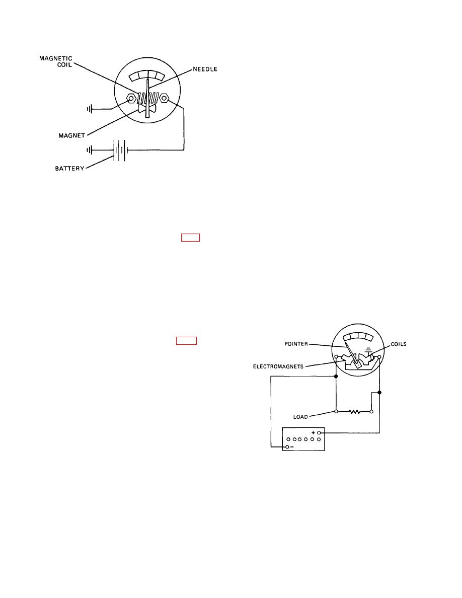
Figure 17-2. Ammeter Operation
in the fuel gage circuit so that the electrical fuel gage
operates only when the ignition switch is on. Operation of
ignored because the average vehicle operator does not
the electrical gage depends on either coil action or
know how to Interpret its readings. The Indicator lamp
thermostatic action.
can be utilized in two different ways to indicate an
electrical system malfunction.
a. Thermostatic Fuel Gage: Self-Regulating (Fig. 17-
6). This gage configuration consists of an instrument
panel gage and an electromechanical sending unit that is
indicator lamp can be set up to warn the operator
located inside of the fuel tank. The instrument panel
whenever the electrical system voltage has dropped
gage contains an electrically heated bimetallic strip that
below the normal operational range. The lamp is
is linked to a pointer. A bimetallic strip consists of two
operated by a calibrated relay that opens the circuit to it
dissimilar metals that, when heated, expand at different
whenever electrical system voltage is in the normal
rates, causing it to deflect or bend. In the case of the
range (13.2 to 14.5 volts for a 12-volt system). Whenever
instrument panel fuel gage, the deflection of the
the voltage falls below the normal range, the magnetic
bimetallic strip will result in the movement of the pointer,
field becomes insufficient to overcome the force of the
causing the gage to give
relay spring, which pulls the contact points closed. This
closes the circuit to the indicator lamp.
indicator lamp also can be set up to indicate whenever
the alternator is not producing current. The circuitry that
operates a no-charge indicator lamp usually is
incorporated in the voltage regulator. The voltage
regulator that is used on a vehicle equipped with a no-
charge indicator lamp contains a second element called
a field relay. The field relay has two contact points. One
contact point is connected to battery voltage through the
ignition switch. The other point also is connected the
same way, except for the inclusion of a series-parallel
arrangement of the no- charge indicator light and a
resistor. The resistor value Is matched with the
resistance of the indicator lamp so that their parallel
arrangement will produce a zero-voltage drop. When the
field relay Is open, alternator field current is supplied
through the resistor-indicator light combination. The
Figure 17-3. Voltmeter Operation
magnetic coil of the field relay is energized
17-2
|
||
 |
||