| Tweet |

Custom Search
|
|

|
||
 TM 9-8000
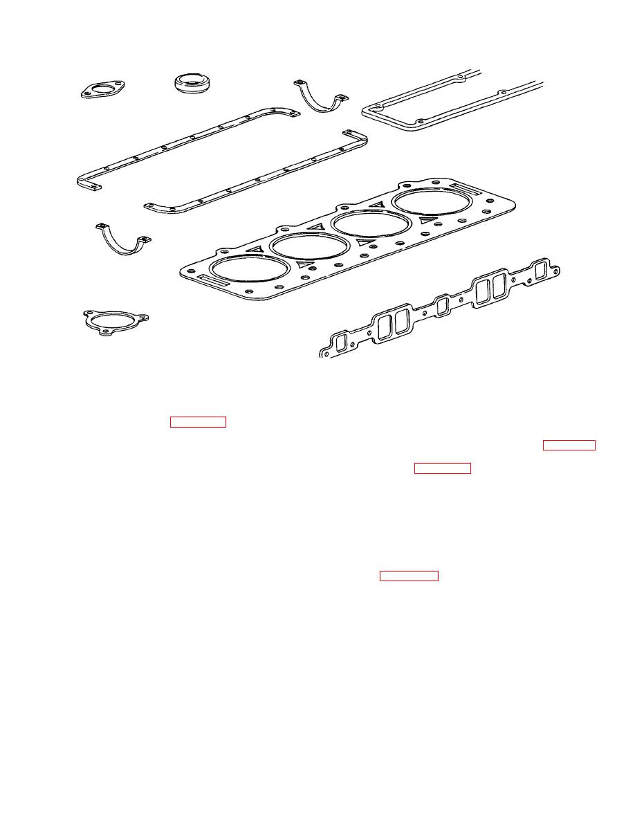
Figure 19-16. Typical Gaskets
Section III. POWER TRAIN CONFIGURATIONS
wheels. Front wheels are designed only to maneuver the
vehicle. Rear-wheel drive vehicles can be powered by an
drive vehicles deliver the driving force of the engine and
engine mounted in front, middle, or rear (fig. 19-18).
transmission to the front wheels only.
In this
The front-mounted design is the most popular. This
configuration, the rear wheels are de- signed to rotate
configuration (fig.
freely. The front-wheel drive arrangement is more
mounted longitudinally with a clutch or torque converter
efficient than other configu- rations for the following two
and transmission mounted after the engine. Power then
reasons:
is delivered to the rear axle by the propeller shaft.
Hypoid gears (para 29-9) generally are used in the rear
a. Power generally is delivered in a straight line.
axle to lower the drive line and allow the body to sit closer
The majority of front-wheel drive vehicles use a
to the ground.
transversely mounted engine. This feature eliminates the
power from being driven through different angles at the
drive axles.
19-15. Four-Wheel Drive. A typical four-wheel drive is
shown in figure 19-19. In this configuration, an engine is
b. The front-wheel drive configuration has fewer
mounted in the front of the vehicle, followed by the clutch
moving parts. This helps reduce friction and increase
and transmission. Power then is delivered to the transfer
engine life.
case, where it is divided between the front and rear
axles. The transfer case also is designed to move the
These features help make the front-wheel drive
front propeller shaft to the right, allowing for engine-to-
configuration one of the most popular designs on modern
drive train clearance. This configuration is very popular
vehicles.
on many smaller heavy-duty vehicles.
19-14.
Rear-Wheel Drive.
The rear-wheel drive
configuration applies the driving force to the rear
TA233663
19-14
|
||
 |
||