| Tweet |

Custom Search
|
|

|
||
 TM 9-8000
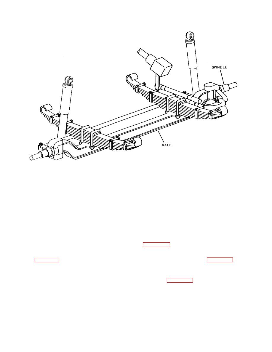
Figure 30-8. Dead Front Axle
Section III. INDEPENDENT AXLE SUSPENSION SYSTEMS
carefully.
30-5. Purpose. The term independent suspension is
applied to a method of vehicle suspension in which each
30-7. Driven Independent Suspensions. The engine
wheel supports its share of the vehicle load without the
intermediary axle. Each wheel is free to oscillate
power is transmitted from the gearcase, which is
independently of the other wheels. Either the front or
attached to the vehicle frame rigidly, through half shafts,
rear wheels, or both, may be suspended independently.
to each wheel. The geometry of the guiding linkage
They may be driven or freewheeling. No one type of
dictates the use of two universal joints. Because the
spring is used for independent suspensions. Leaf, coil
gearbox is fastened to the frame rigidly, the driving
torsion bar, torsi-elastic, and pneumatic springs have
torque reactions are taken through the frame and do not
been used. A variety of mechanisms have been devised
affect the suspension spring.
in implementing the independent suspension.
heavy multiwheeled vehicle.
30-6. Freewheeling Independent Suspensions. A
typical independent front suspension for a light vehicle is
This design is similar to that of figure 30-11, except that
shown in figure 30-9. In this design, each wheel is held
torsion bar springs are used in place of coil springs.
in alinement by a pair of stiff control arms, commonly
called parallel wish-bones.
The vehicle weight is
An independent rear suspension employing coil springs
transferred from the frame to the rigidly attached
is shown in figure 30-12. In this design, the alinement of
crossmember, through the coil spring, to the lower
each wheel is maintained by a
wishbone. It may be noted that the control arms are of
unequal lengths. The vehicle designer may achieve
certain
desirable
suspension
and
cornering
characteristics by selecting the control arm lengths
TA233804
30-6
|
||
 |
||