
| Tweet |

Custom Search
|
|

|
||
 TM 9-8000
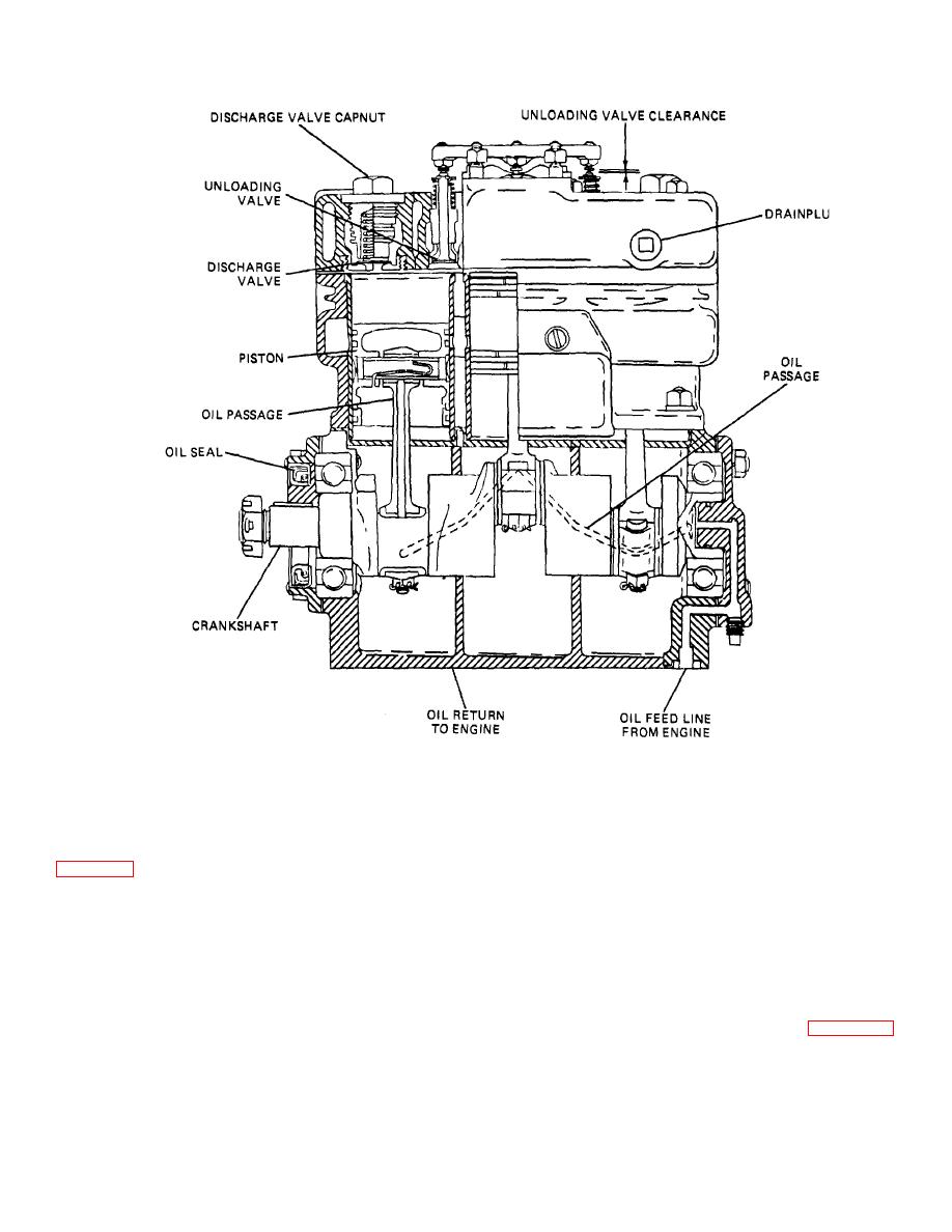
Figure 34-33. Typical Air Compressor, Three-Cylinder.
d. Airbrake valve. The airbrake valve lever Is
force exerted on top of the diaphragm, the diaphragm
lifts sufficiently to close the intake valve and maintain the
connected to the brake pedal. Movement of the lever
system in the holding position. Further depression of the
controls the operation of the Inlet and exhaust valves
pedal puts additional mechanical force on the
diaphragm, thereby allowing further brake application. If
to or released from the brake chambers. As the brake
the driver releases the brake pedal, reducing the
pedal is de- pressed, the brake valve lever moves toward
mechanical force on the diaphragm, the Inlet valve
its applied position. The plunger and regulating spring
remains closed, while the exhaust valve opens to allow
are forced down, applying mechanical force on the
the air under pressure to be exhausted from the brake
diaphragm. The exhaust valve spring Is weaker than the
chambers to release the brakes.
Intake valve spring, so the exhaust valve is forced
downward onto its seat before the Intake valve Is
opened. When the intake valve opens, air from the
e. Brake Chamber. The brake chamber (fig. 34-36)
reservoir Is allowed to flow through the brake valve to the
converts the energy of the compressed air Into
brake chambers to apply the brakes. When the air
mechanical force to operate the brakes. Air
pressure below the diaphragm overcomes the
TA233882
mechanical
34-36
|
||
|
||


