
| Tweet |

Custom Search
|
|

|
||
 TM 9-8000
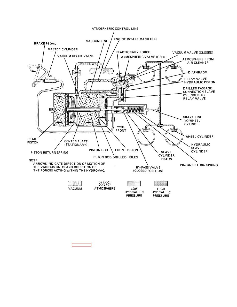
Figure 34-42. Vacuum-Over-Hydraulic Brake System - Applied.
depressed, the bronze lever comes in successive
Section XI. 34-44. Construction. The electric brake
contact with leaves of varying lengths and completes the
system, which operates from the storage battery or the
electric circuit from the battery to an electromagnet in the
electrical system, is quite simple. Wiring replaces the
brake.
rods, cables, and tubings used in other types of brakes.
The controller can be mounted at any convenient place
Electric current is supplied to the electromagnet, the
in the driver's compartment. It usually is attached to the
amount depending on the number of leaves contacted by
steering column. A bronze lever (fig. 34-43) within the
the bronze lever. When the brake is fully depressed, all
controller, connected by linkage to the brake pedal, acts
the leaves are in contact with the bronze lever and the
as a rheostat switch. The controller is provided with
maximum amount of current flows to the brake.
electrical terminals to connect it in the electric brake
TA233888
circuit. As the brake pedal is
34-43
|
||
|
||


