
| Tweet |

Custom Search
|
|

|
||
 TM 9-8000
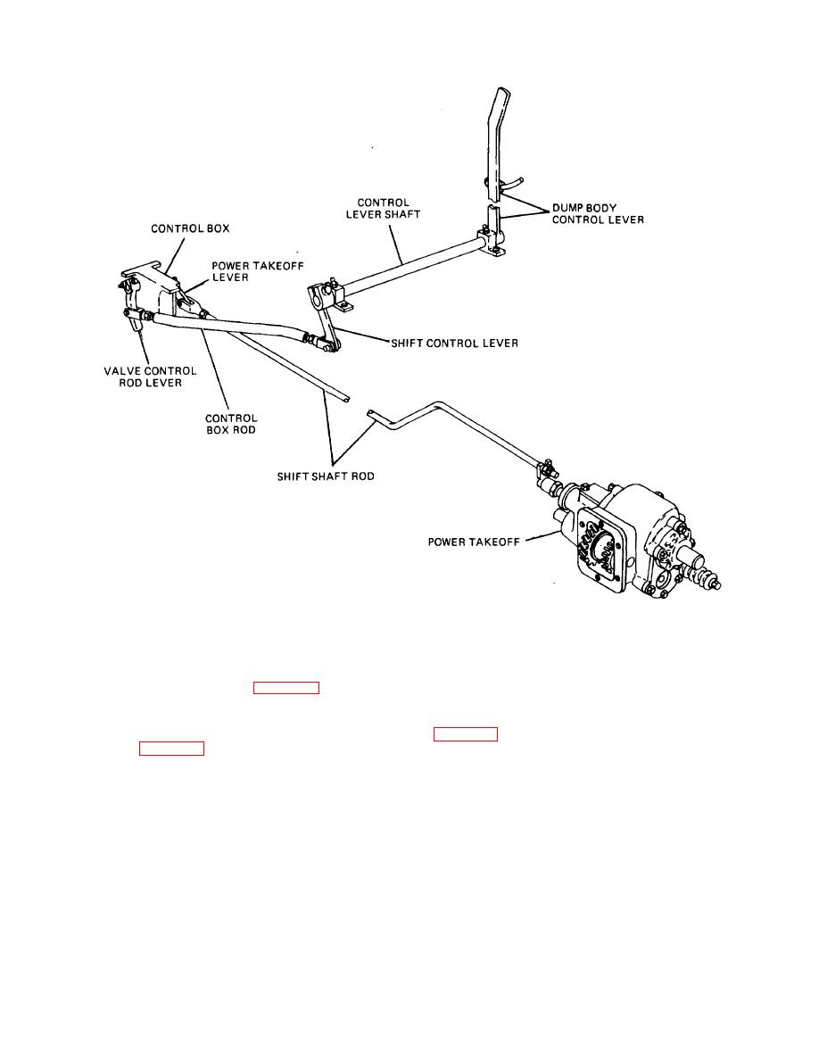
Figure 36-16. Control Linkage Between Control Lever, Control Box, and Power Takeoff.
Section VI. WRECKER TRUCK EQUIPMENT
36-23. Operation. The various mechanisms
front and rear winches and a crane assembly. Winches
incorporated in the crane are driven by the engine
are described in paragraph 36-7. The crane assembly
through a center propeller shaft. The main drive chain
consists of a combination of units, all mounted on the
crane A-frame (fig. 36-18). The units include the boom,
shaft to the hoist gearcase, boom gearcase, and swinger
boom pivot and controls, topping pivot, boom winch and
gearcase input sprocket. Each gearcase has its own
controls, crane winch, crane winch drive and controls,
control lever and control system. With these controls,
crane winch transmission, and center propeller shaft with
the boom may be raised or lowered, it may be pivoted,
connecting parts. All of these units are essential to the
and the crane winch can be made to rotate in one
operation of the crane. There are other units mounted on
direction or the other in order to raise or lower the load.
the A-frame which are not part of the crane, including the
rear winch, rear winch drive, rear winch transmission,
and front winch jaw clutch.
TA233905
36-12
|
||
|
||


