TM 5-2815-241-34&P
VALVE AND INJECTOR ADJUSTMENTS - CONTINUED
ACTION
LOCATION
ITEM
REMARKS
NOTE
With accessory drive pulley timing mark at A or 1-6 VS, number three injector has been
adjusted. Valves in number five cylinder now must be adjusted.
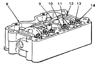
15. Rocker arm
housing (8)
Intake rocker arm
(9), locknut (10), and
adjusting screw (11)
a.
Using 3/8-inch drive ST-669 adapter
set, and 1/4-inch drive 7/16-inch
socket, loosen locknut and unscrew
adjusting screw.
b.
Using thickness gage, put in between
rocker arm and crosshead.
Clearance should be 0.011 inch
(0.28 mm).
c.
Using 3/8-inch drive ST-669 adapter set
and 0 to 150 ft lb (0 to 210 N•m) torque
wrench, torque to 25 to 35 ft lb (35 to
49 N•m).
16.
Exhaust rocker arm
Perform same adjustment procedures de-
(12), locknut (13),
scribed in step 15.
and adjusting
Clearance should be 0.023 Inch
screw (14)
(0.58 mm).
NOTE
Repeat steps 5 thru 16 as per Injector and Valve Set Position table below.
INJECTOR AND VALVE SET POSITION
ADJUST
CYLINDER
ROTATION
PULLEY
DIRECTION
POSITION
INJECTOR
V A L V E
Start
1-6 “ V S ”
3
5
Advance t o
2-5 “ V S ”
6
3
Advance to
3-4 “ V S ”
2
6
Advance t o
1-6 “ V S ”
4
2
Advance t o
2-5 “ V S ”
1
4
Advance t o
3-4 “ V S ”
5
1
NOTE: Two complete revolutions of the pulley are required
to adjust all injectors and valves.
T A 2 4 2 4 0 4
2-111
|
|