TM9-2815-202-34
(43)
(44)
(45)
(46)
(47)
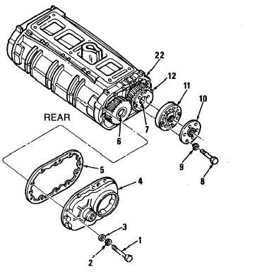
Check clearances at points (D) and (E). Insert feeler gages between lobes of rotors (6 and 7)
and blower housing (29). Measure clearance for each lobe at both inlet and outlet side (total
of twelve). Minimum clearance at (D) is 0.015 inch and at (E) is 0.004 inch.
Place blower assembly on end on two wood blocks with gear end up. Place blower drive
coupling (1 O) on gear (12) with groove inside coupling next to gear. Install coupling, retainer
(11 ), six bolts (8), and six Iockwashers (9) to gear(11 ). Insert folded rag between rotors (6
and 7). Torque bolts to 20-25 Ib-ft (27-34 N-m). Remove rag.
Using dial indicator, measure cam spline runout. Maximum runout must not exceed 0.020
inch total indicator reading.
Remove four bolts and four flat washers holding each end plate to blower housing (installed
to check blower clearances).
Position gasket (5) on blower rear end plate cover (4) and loosely secure cover and gasket
to rear end plate (22) with ten bolts (1), ten Iockwashers (2), and ten special washers (3).
NOTE
Whenever installing a tachometer drive cover assembly or drive adaptor, maintain
proper alinement between cover and tachometer drive shaft. Correct alinement is when
no binding occurs between drive shaft and inside diameter of alinement tool when
rotating blower rotors.
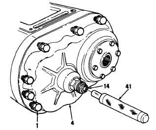
(48) Using tachometer drive alinement set (41), aline cover (4) with tachometer drive shaft (14) by
.
.
selecting tool with best fit. Torque bolts (1) to 13-17 Ib-ft (1 8-23 N-m).
END OF TASK
FOLLOW-ON MAINTENANCE
Para Description
4-12 Install fuel pump
4-17 Install governor cover and throttle
control rod
4-18 Install governor and blower assembly
4-247
|
|