TM 9-2815-202-34
5.1-36. TURBOCHARGER REPAIR (Cont)
(12)
(13)
(14)
(15)
(16)
(17)
(18)
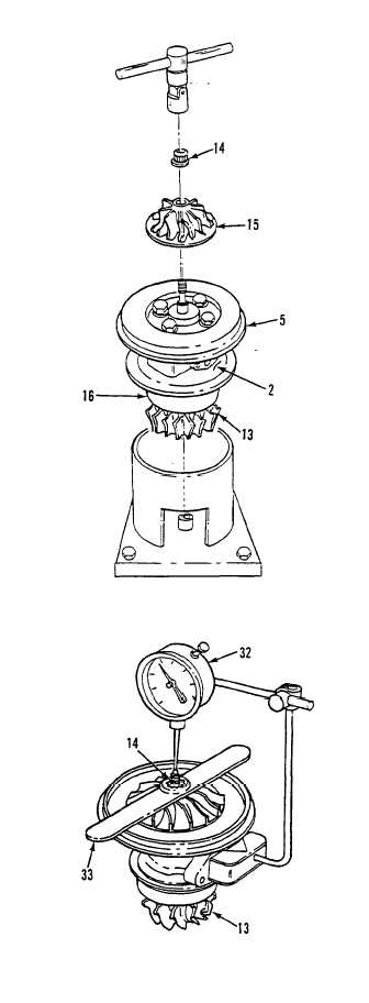
Place turbine wheel shaft assembly
(13), shroud (16), center housing (2),
and backplate (5) upright in
turbocharger holding fixture.
With compressor wheel (15) at room
temperature, position it over turbine
wheel shaft assembly (13).
CAUTION
When torquing compressor
wheel nut on shaft, use two
universal joints connected in
tandem or a single universal joint
and a universal socket to
prevent bending turbine wheel
shaft.
Lubricate shaft threads of turbine wheel
shaft assembly (13) and wheel face on
compressor wheel (15) with engine oil.
Install self-locking nut (14). Torque nut
to 125-150 lb-in (14-17 N-m) to seat
compressor wheel against thrust
spacer.
Loosen self-locking nut (14) and inspect
nut face and front face of compressor
wheel to insure they are smooth and
clean.
Torque self-locking nut (14) to 35-55
lb-in (4-6 N-m).
Attach magnetic base dial indicator (32)
to center housing.
Place impeller nut box wrench (33) on
impeller nut (14) and position dial
indicator on tip of turbine shaft
assembly (13). Set dial indicator to zero.
Tighten nut to obtain shaft stretch of
0.009-0.010 inch.
5-100
Change 1
|
|