ARMY TM 9-2815-255-24
AIR FORCE TO 38G1-95-2
MARINE CORPS TM 2815-24/4
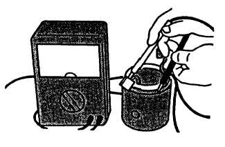
e.
Using a multimeter, touch one probe to field winding end of brush and other one to bare surface of yoke body,
refer to FIGURE 3-22. There should be no continuity. If there is continuity, field windings are grounded.
Replace the yoke assembly.
FIGURE 3-22. Checking Field Coils
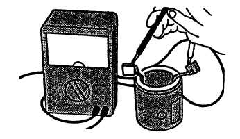
f.
Using a multimeter, touch one probe to lead wire and other one to brush, refer to FIGURE 3-23. There should be
continuity. If there is no continuity, field windings are open circuited. Replace the yoke assembly.
FIGURE 3-23. Checking for Open Field Coil
3-12.6. Assembly.
a.
Install contact (42, FIGURE 3-15), end plate (41), washers (40), and screws (39) in magnetic switch assembly
(24).
b.
If removed, install nuts (26 and 27), washers (28 thru 30), lockwashers (31 and 32), and screw (25)
c.
Apply general purpose grease (630AA) to retainer (20), rollers (21), overrunning clutch (17), steel ball (18), spring
(23), and bearings (33 and 34).
d.
Install washer (22) and spring (23) in magnetic switch assembly (24).
Change 3 3-41
|
|